SPOT Rollik 150 Instructions d'utilisation

1
Rollik 150 Frame
Assembly Instrucons and Maintenance Manual

2
Table of Contents
Warnings and Precauons
Component Compability Chart
Tools Required for Assembly of Components onto Frame
A. Geometry Adjustment
B. Internal Dropper Seatpost Roung
C. Rear Brake Hose Roung
D. Rear Derailleur Cable Roung
E. Boom Bracket Installaon
Tools Required for Maintenance
Leaf Spring Related Precauons
F. Rear Derailleur Hanger Removal/Replacement
G. Rear Shock Removal/Replacement
H. Rear Triangle Removal
I. Upper Link Removal
J. Main Pivot Bearing Replacement
K. Upper Link Bearing Replacement
L. Shock Yoke Bearing Replacement
M. Reinstalling the Upper Link
N. Reinstalling the Rear Triangle
Rollik Frame Parts Reference / Exploded View
3
3
4
5
8
10
10
13
14
15
16
17
18
23
24
26
28
29
32
41
3
Rollik 150 Component Compability
Your Rollik 150 frame was designed to work with the following components. Other components
may be compable, but tment is not guaranteed. For quesons regarding component compa-
bility for parts not listed below please contact Spot.
Warning
Like any sport, bicycling involves risk of injury and damage. By choosing to ride a bicycle, you as-
sume the responsibility for that risk, so you need to know—and to pracce— the rules of safe and
responsible riding and of proper use and maintenance. Proper use and maintenance of your bicy-
cle reduces the risk of injury or death.
All bicycles should be assembled and maintained by an authorized bicycle mechanic. If you are not
qualied to assemble, inspect, and maintain your bicycle, please visit your favorite local bike shop
or contact Spot Brand for a referral to a qualied bicycle technician in your area.
This guide covers the details specic to working with your Living Link™ frame. It does not address
complete bicycle assembly, ng, inspecon, maintenance, or riding techniques. Please refer to
the Spot Brand Bicycle Owner’s Manual for further details.
Under no circumstances shall Spot Brand LLC be held liable for direct, incidental, or consequenal
damages, including, without limitaon, damages for personal injury, property damage, or econom-
ic losses, whether based on contract, warranty, negligence, product liability, or any other theory.
COMPONENT FIT/STANDARD
HEADSET UPPER: ZS44, LOWER: ZS56
BOTTOM BRACKET 73mm THREADED
SEATPOST Ø31.6, INTERNAL DROPPER ROUTING
1X DRIVETRAIN 52mm "BOOST" CHAINLINE REQUIRED, DIRECT MOUNT CHAINRING REQUIRED, 34t MAX
REAR HUB 12 X 148mm, SRAM MAXLE REAR AXLE INCLUDED
REAR BRAKE Ø160 NATIVE POST MOUNT, Ø180mm MAX ROTOR DIAMETER
REAR TIRE 29 X 2.6" / 66mm MAX WIDTH, Ø710mm MAX DIAMETER. NOTE THAT ACTUAL TIRE WIDTHS
CAN VARY FROM PRINTED SIZES
REAR SHOCK 210 X 55, FRONT EYELET: Ø8 X 20, REAR EYELET OPEN Ø12.7 BUSHING
SEATPOST COLLAR Ø35.0mm
FORK TRAVEL 150-160mm
WATER BOTTLE 2X BOTTLE MOUNTS, ONE ABOVE AND ONE BELOW THE DOWNTUBE
CHAIN GUIDE ISCG-05 TABS, LARGE UPPER GUIDES MAY NOT FIT. CONTACT SPOT FOR RECOMMENDATIONS

4
Geometry Adjustment
Tools Required:
• L or T-shaped T-25 Torx wrench
• 10mm box end (12-point) wrench
Assembly
Tools Required:
• Hex wrenches / bits, sizes: 5mm, 6mm
• Torx wrenches / bits, sizes: T25, T30
• Torque wrench
• Headset Press
• Boom Bracket Installaon Tools—May vary by BB brand and model
• High-Lubricity Waterproof Grease—We recommend Slick Honey
• Isopropyl or denatured alcohol—90% or higher concentraon
• Strong, thin adhesive tape—electrical tape, packaging tape, etc.
5
The Rollik 150 frame incorporates a novel system to quickly adjust the geometry between two dierent
sengs or modes. The normal mode is useful as an all-around trail seng, providing a useful amount of
pedal clearance for rocky terrain and nimble steering at most climbing and descending speeds. The low
mode sacrices some pedal clearance for a lower center of gravity and more precise steering at high
speeds. To switch between the two modes, follow these steps:
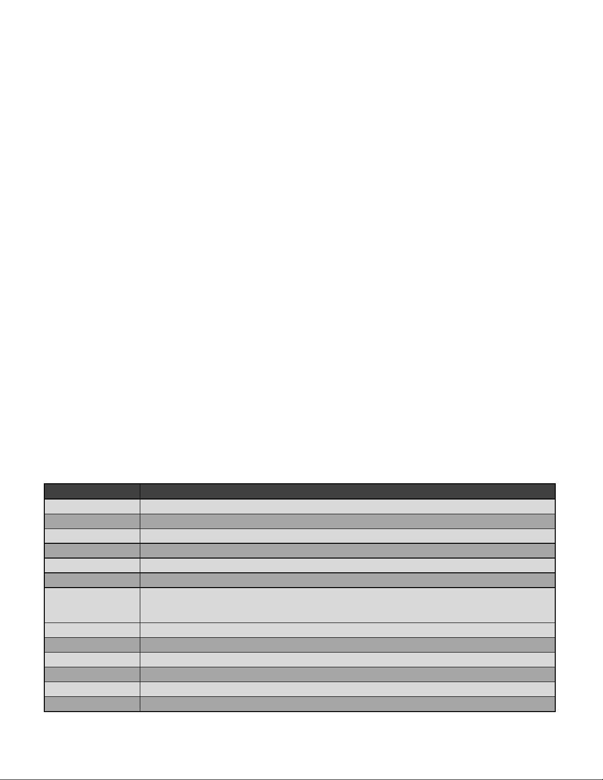
1. Unscrew the rear shock mount screw 3 full turns (1080°) using a 10mm box end wrench:
A. Geometry Adjustment
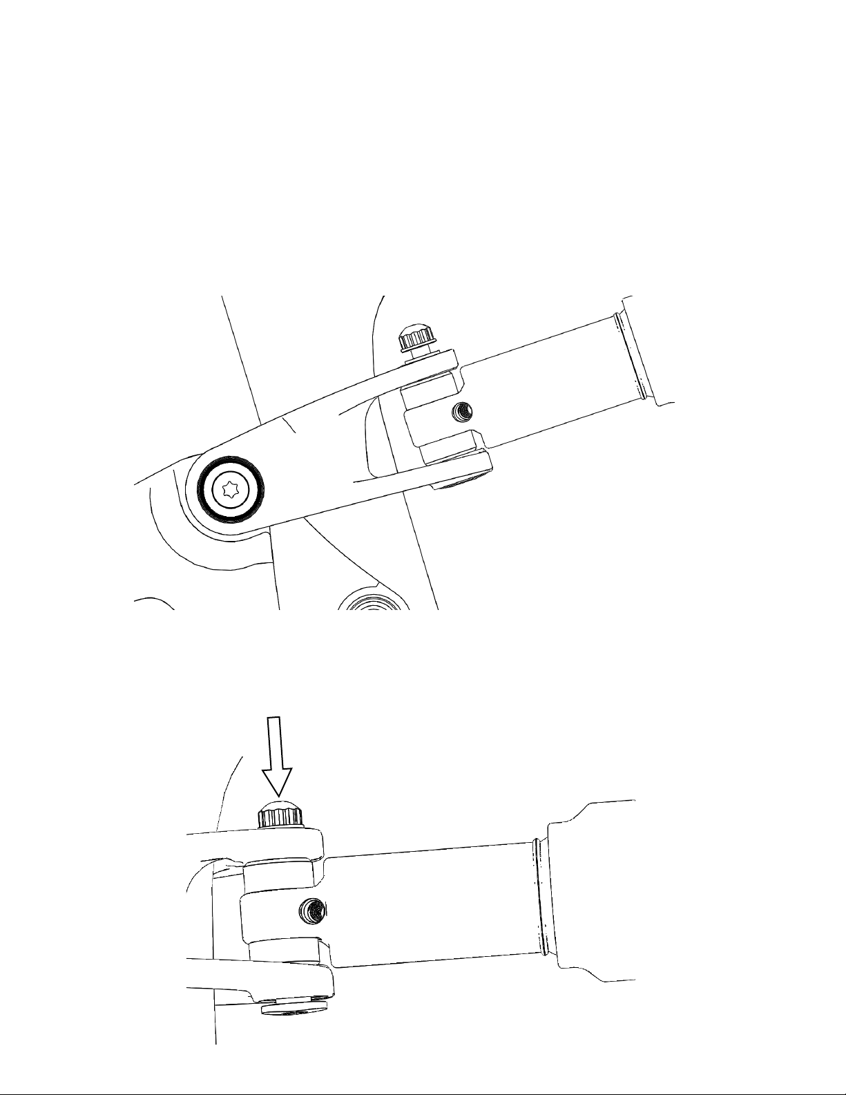
2. Push downward on the screw to free the oval shaped head of the shock pin from its recess on
the shock yoke:
6
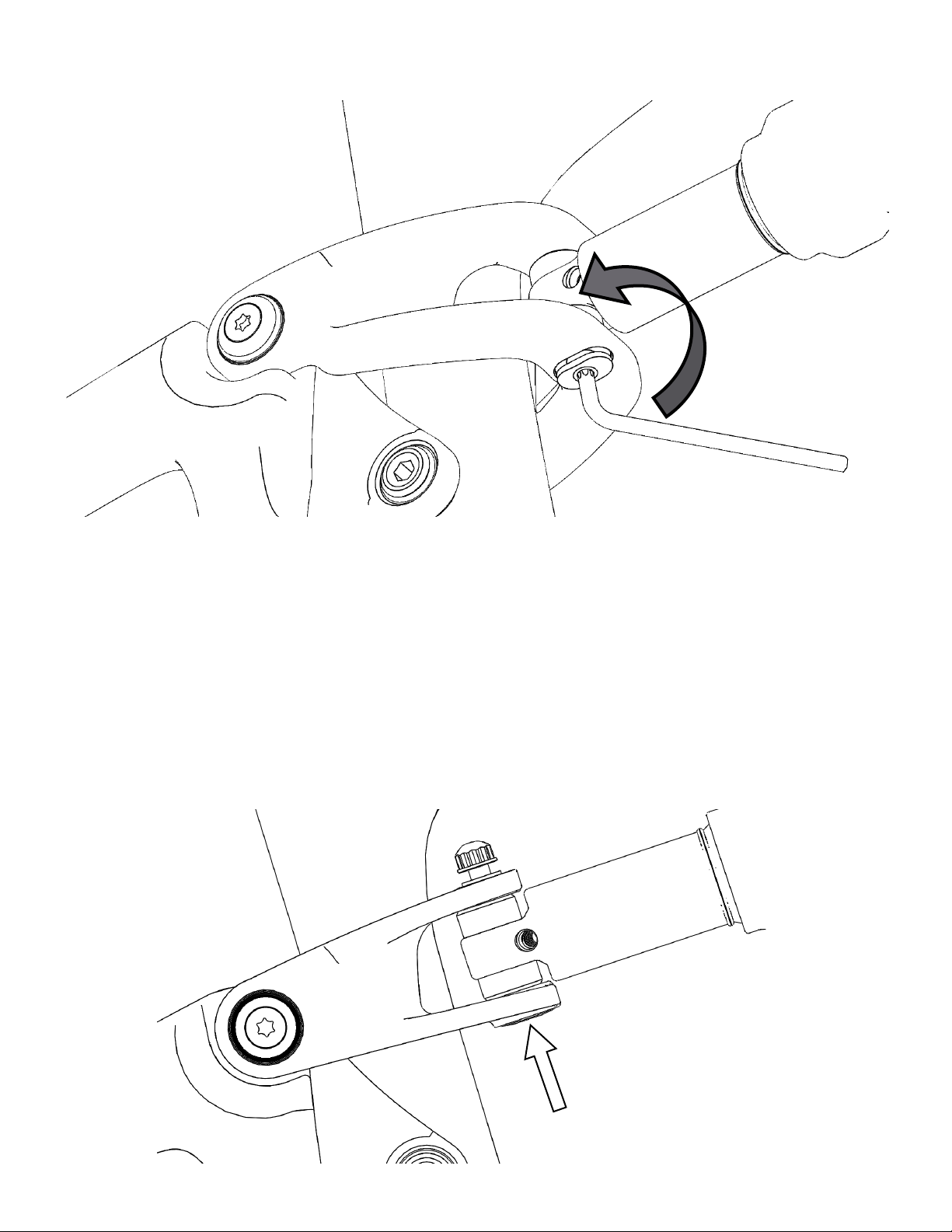
3. Turn the shock pivot pin 1/2 turn (180°) using a T25 Torx tool. Direcon of rotaon does not maer:
4. Push upward on the oval shaped head of the shock pin to return it to its recess in the shock yoke
and ghten the shock mount screw using a 10mm box end wrench. Torque 10Nm (80in-lb). Do
not overghten:

7
Once familiar with the operaon of the geometry adjuster, a visual check should be enough to determine
the geometry mode. However, it may be necessary to perform the adjustment to conrm its posion.
Low mode– front edge of eyelet reducer is set back away from front surface of yoke:
Mode Idencaon
Normal mode– front edge of eyelet reducer lines up with front surface of yoke:
GEOMETRY ADJUSTMENT PARAMETERS
MODE HEAD TUBE ANGLE BOTTOM BRACKET HEIGHT
NORMAL 66.4° 343mm / 13.50in
LOW 65.8° 336mm / 13.23in
8
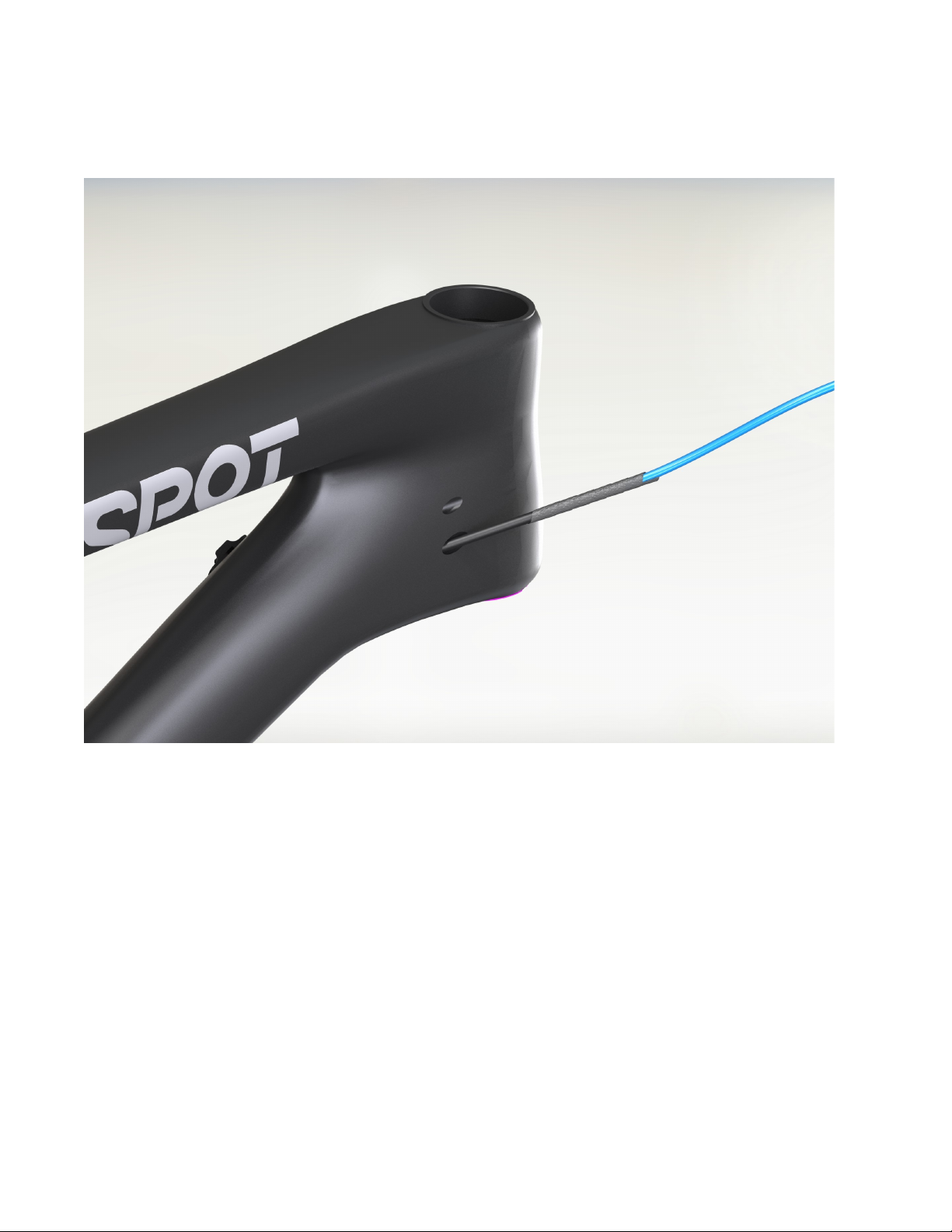
1. Make sure your seatpost collar is installed on the frame. The seatpost cable/hose is easiest to
install by feeding from the seat tube to the head tube, but can be fed starng at the head
tube if necessary. Tape the seatpost cable housing or hydraulic hose to the lead tube at the
seat tube end. Make sure to clean the end of the cable/hose and the lead tube with alcohol
before taping. Tape the two together in line, and wrap the tape several mes around the
juncon for sucient contact.
2. While feeding the seatpost cable/hose into the seat tube, gently pull the lead tube out of the
port near the head tube. If excessive resistance is met, the tape joint may be too bulky and
should be reduced. The cable/hose must curve around a relavely small radius between the
seat tube and the down tube. It is recommended to help the seatpost cable/hose around this
curve with a nger or two through the access port in the BB shell.
B. Internal Dropper Seatpost Roung
IMPORTANT:
Install your internal dropper seatpost cable/hose before installing the boom bracket assem-
bly. Your Rollik 150 frame is supplied with a lead tube installed in place of the dropper seatpost
cable/hose to ease installaon. Please do not remove the lead tube unl the dropper seatpost
cable is installed.
9
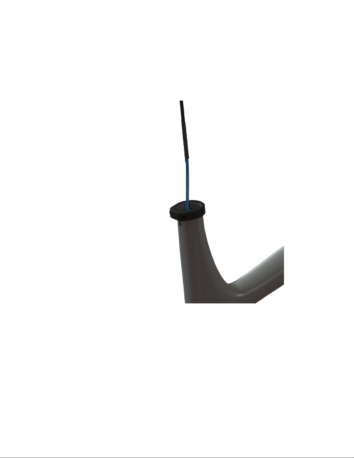
3. Connue to feed the seatpost cable/hose while gently pulling the lead tube from the port
near the head tube. When the seatpost cable emerges from the port, remove the tape and
store the lead tube in a safe place:
4. Proceed to install your dropper seatpost per the seatpost manufacturer’s instrucons. You
may wish to install other components on the frame before compleng the dropper post instal-
laon.
10
C. Rear Brake Hose Roung
1. Begin by installing the rear brake caliper and any applicable adapter if using a rotor larger
than 160mm. Please note the Rollik 150 frame is not compable with rotors larger than
180mm.
2. Route the rear brake line starng from the caliper- aaching it to the rear triangle using the
supplied zip es on the cable saddles, and the screw in the p-clip.
3. Leaving a small amount of slack between the p-clip and the front triangle, connue to route
the line up the down tube using the supplied zip es.
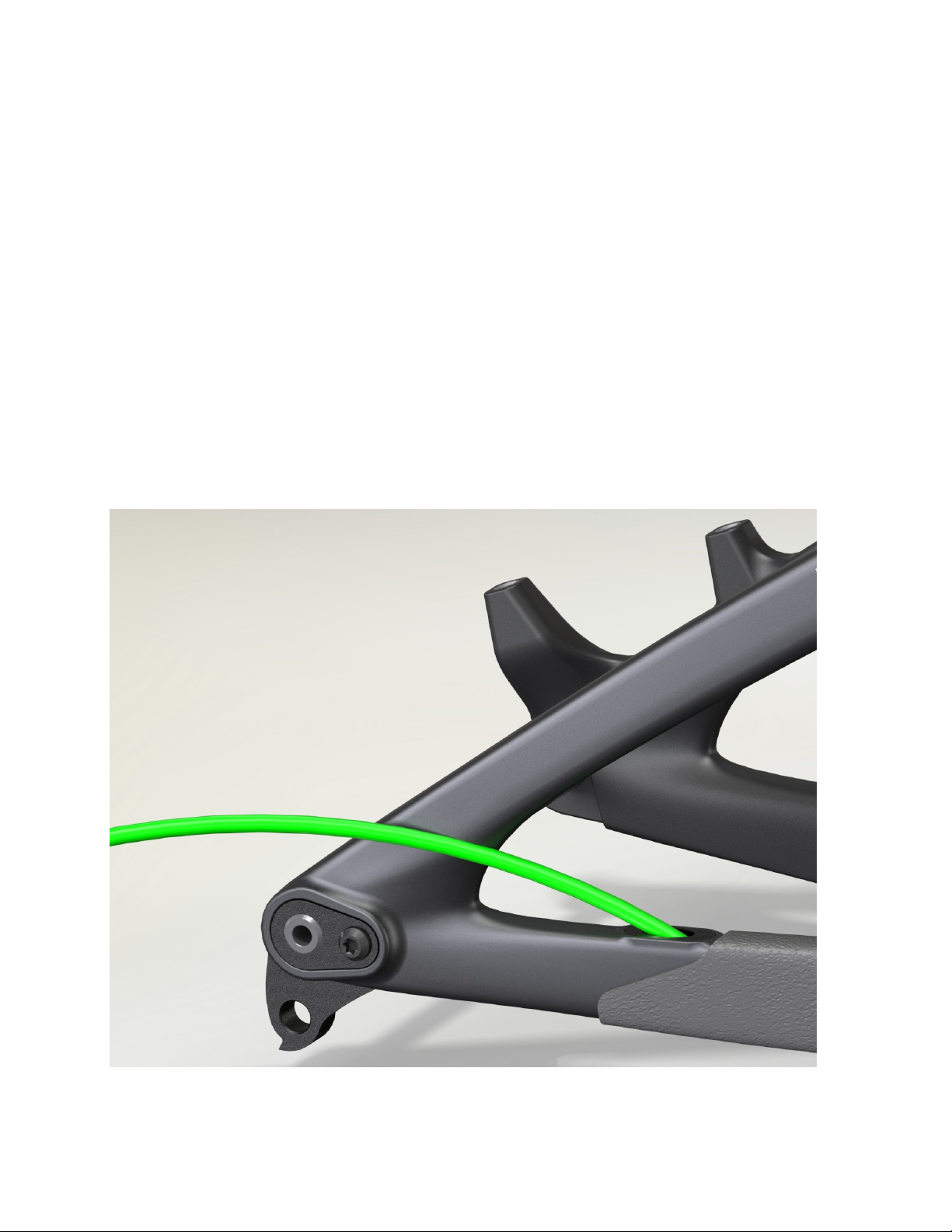
D. Rear Derailleur Cable Roung
1. Begin by feeding the rear derailleur cable housing into the rear port on the top of the drive
side chainstay near the rear axle. It will emerge from the forward port on the chainstay yoke
behind the boom bracket:
Table des matières
Autres manuels SPOT Accessoires pour vélos


