Sponge-Jet 35E Manuel utilisateur

SPONGE-JET 35E 50E USER MANUAL | 1
SPONGE-JET®
35E RecyclerTM
50E RecyclerTM
USER MANUAL
Sponge-Jet, Inc. (USA)
14 Patterson Lane +1-603-610-7950
Newington, NH 03801 www.spongejet.com
Sponge-Jet 35P 50E User Manual - REV B/ ENG

2| SPONGE-JET 35E 50E USER MANUAL
CONTENTS
1.0 Safety 3
2.0 Basic Components 5
3.0 Receipt and Inspection 8
4.0 Media Classification 9
5.0 Electrical Requirements 11
6.0 Normal Operation 12
7.0 Advanced Operation 13
8.0 Routine Maintenance 16
9.0 Rebuild Maintenance 17
Notes 19
IMPORTANT NOTE: While parts, systems, components, operational
procedures may be the same between equipment models, the images
provided in this manual may vary from model to model.
This manual represents the following models:
Model: 35E Weight: 148 kg (325 lb)
Model: 50E Weight: 170 kg (375 lb)
English Language is Original Instructions.
Translated from Original Instructions.

SPONGE-JET 35E 50E USER MANUAL | 3
1.0 SAFETY
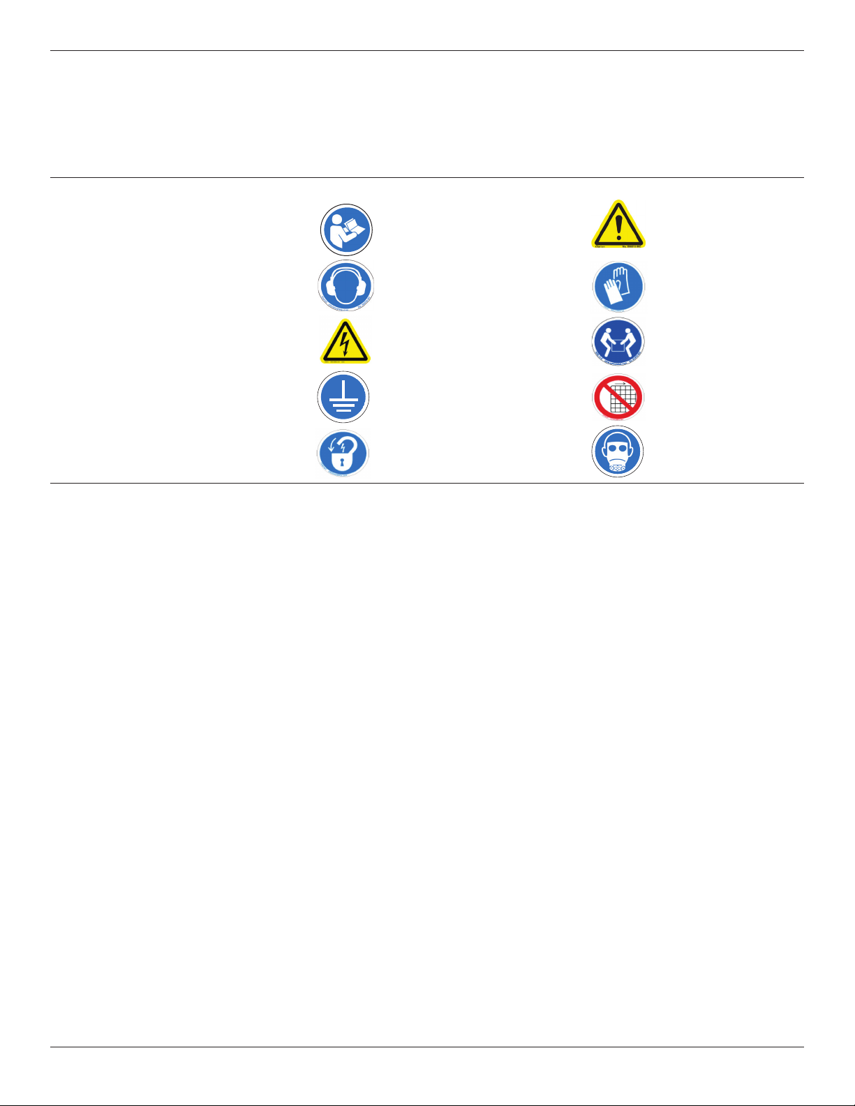
Safety Labels
User Manual Caution/Danger
Ear protection Safety Gloves
Hazardous Voltage Two Man Lift
Protective Earth Ground Do Not Operate with
Guards Removed
Lockout/Tagout Eye Protection
Electrical Power Respiratory Protection
Failure to follow all Instructions in manual and any alterations made to
equipment following shipment from Sponge-Jet will void warranty. Direct
attachment, such as welding or bolting of any additional chutes or hoppers,
etc., to vibrating equipment other than those supplied by Sponge-Jet, Inc.
will automatically void warranty.
Any connection made to unit must be flexible.
Before starting unit, operator must be certain unit is free to follow
movement produced by vibrating parts.
In general, feeding and discharge connections must have sucient
clearance to prevent any contact.
Before Starting Unit:
The base must have a substantial foundation around entire bottom of the unit
base ring. The base must be secured to floor or adequate support structure
unless on casters. If, after unit has been started, there are secondary vibra-
tions to foundation or to separator base, unit must be reinforced. With further
questions, consult Sponge-Jet, Inc.
Shipping lugs must be removed.

4| SPONGE-JET 35E 50E USER MANUAL
1. All guards and service doors must be in place.
2. Risks:
a. Operating equipment with guards removed
b. Hazardous voltage
3. Required Personal Protective Equipment:
a. Wear eye protection
b. Wear ear protection
c. Wear safety gloves
d. Wear respiratory protection
4. Unit should only to be operated and maintained by trained personnel.
a. Read and follow all maintenance instructions and guidelines.
User should not operate without reading all guidelines.
b. Licensed electrician for wiring of any electrical equipment is required.
5. Unit must not be used:
a. Do not operate with explosive products or products at
elevated temperatures.
b. Do not operate without all guards and covers in place.
c. Lockout/tagout procedures must be followed before any
inspection, maintenance or cleaning is undertaken.
d. Lockout/tagout procedures must be followed before
adjustments are made to eccentric weight mechanism.
e. User must ensure any cables, hoses or pipes do not
present a slip, trip or fall hazard.
f. Unit should not be climbed on.
g. User is responsible for taking all necessary precautions
dependent on material being screened.
h. Be careful when moving. Move with help.

SPONGE-JET 35E 50E USER MANUAL | 5
2.0 BASIC COMPONENTS
1 Hopper
2 Main Rim
3 Vibratory Section
4 Safety Skirt
5 Large Particle Downspout
6 Reusable Media Downspout
7 Fine Particle Downspout
8 Pan Clamp Hook
9 Pan Clamp
10 Caster
11 On/O Switch
12 Motor
7
9
10
5
1
2
3
4
6
11
12
8

BASIC COMPONENTS (CONTINUED)
Figure A: Sieve Assembly
1Hopper
2Flat Gasket
3Large Particle Downspout
Oversized particles that cannot pass through top screen are discharged through
Large Particle Downspout.
4Top Screen
Stainless Steel mesh screen used to separate oversized items larger than Sponge
Media particle from reusable Sponge Media.
(See section 7.5 Sieve Assembly, for proper screen installation)
5Reusable Media Downspout
Particles that do not fall through Bottom Screen are discharged through Reusable
Media Downspout.
6Bottom Screen
Stainless Steel mesh screen used to separate undersized material (normally con-
sidered waste) from reusable Sponge Media abrasive.
(See section 7.5 Sieve Assembly, for proper screen installation)
7Fine Particle Downspout
Particles that fall through bottom screen are discharged through Fine Particle
Downspout.
8Shallow Funnel
Located under the Bottom Screen, the shallow funnel collects and directs fine particu-
late (waste) into Fine Particle Downspout.
Figure B: Vibratory Portion and Lower Base Assembly
1Flywheel
Vibratory energy generated directly by Flywheel is transmitted to Sieve Assembly.
2Vibratory Portion
Is located over Lower Base Assembly and supports Sieve Assembly.
3Suspension Rod
Vibratory Portion is located over Lower Base Assembly and supports Sieve Assem-
bly.
4Weight
This o center weight causes upper the eccentric Flywheel to move media across
screen.
5Side Cover
This removable cover serves as protection for the components located inside the
Lower Base Assembly.
6Lower Base Assembly
Supports Main Controls, Air Motor, Vibratory Portion and Sieve Assembly.
7Flexible Coupling
Absorbs startup torque from electric motor and passes that energy up through
Vibratory Portion.
1
3
5
6
7
2
2
4
2
2
8
6| SPONGE-JET 35E 50E USER MANUAL
2
34
5
1
7
6

SPONGE-JET 35E 50E USER MANUAL | 7
BASIC COMPONENTS (CONTINUED)
Figure C: Pan Clamps
1Pan Clamp Hook
Adjustment for varying sized gaskets is made by turning Pan Clamp Hook.
2Lock Nut
Used to prevent Pan Clamp Hook from swiveling when dismounting Pan Clamps
(50E only).
3Threaded Rod
Pan Clamp Hook threads onto Threaded Rod.
4Handle
Used to secure Pan Clamp to Sieve Assembly.
1
2
3
4

8| SPONGE-JET 35E 50E USER MANUAL
3.0 RECEIPT & INSPECTION
Upon receipt of shipment, review packing list, immediately check for missing
or damaged parts; open all boxes and crates, and/or any abnormalities; if
missing/broken parts, promptly notify appropriate carrier and your Sponge-
Jet representative.
- Examine all screens and components to insure damage has not occurred
during shipment.
- Operate unit on a sturdy, flat surface. This will assure maximum eciency.
- Vibrating parts should never come in contact with static parts of unit or its
surroundings.
- Check to be sure screen elements are level.

SPONGE-JET 35E 50E USER MANUAL | 9
4.0 MEDIA CLASSIFICATION
Media Classification Process:
(1) Connect unit to an adequate electric supply, and turn on.
(2) After blasting Sponge Media abrasive, collect and pour it into Hopper.
(3) Sponge Media abrasives and small contaminants pass through Top
Screen, while oversized particles exit via Large Particle Downspout.
(4) Spent Sponge Media abrasives and small contaminants pass below
Bottom Screen, and exit through Fine Particle Downspout, while
reusable-sized Sponge Media abrasives exit above Bottom Screen via
Reusable Media Downspout.
IMPORTANT: Proper separation of oversized and undersized particles from
reusable Sponge Media™ abrasive is critical to reducing airborne dust and
minimizing risk of clogging Sponge-Jet Feed Unit™ while blasting.
BOTTOM SCREEN
LARGE PARTICLE
DOWNSPOUT
FINE PARTICLE
DOWNSPOUT
REUSABLE MEDIA
DOWNSPOUT
2
2
3TOP SCREEN
WASTE
HOPPER
WASTE
REUSABLE
SPONGE MEDIA
4

10 | SPONGE-JET 35E 50E USER MANUAL
4.1 TOP SCREEN - LARGE PARTICLE
CLASSIFICATION
Top Screen is a standard #3 mesh screen used to separate unwanted foreign
matter larger than most Sponge Media particles. Items such as nuts, bolts
or rocks are separated and discharged as oversized particles through Large
Particle Downspout.
WARNING:
Oversize particles, if re-introduced back into Working Mix, can cause harm or
damage by (1) becoming a projectile capable of injuring people, (2) harming
work surface, (3) piercing pressurized blast hose, (4) clogging Feed Unit and/
or (5) damaging/jamming the drive mechanism.
4.2 REUSABLE MEDIA
Sponge Media that do not pass through Bottom Screen exit unit via Reusable
Media Downspout. Sponge Media abrasive that exit Reusable Media Down-
spout can be reused in Sponge-Jet Feed Unit.
Working Mix: a blend of blasted Sponge Media passed through Recycler (as
reusable Sponge Media) plus a quantity of new Sponge Media added every 2-3
passes through Recycler. Generally this is 1-2 bags per hour, per nozzle.
4.3 BOTTOM SCREEN - FINE PARTICLE
CLASSIFICATION
Bottom Screen is a number #16 mesh screen used to separate foreign mat-
ter smaller than most Sponge Media particles. Fine particles are separated
from Sponge Media and discharged through Fine Particle Downspout and are
normally considered waste. Fine particles usually include paint chips, broken
down (spent) Sponge Media. These fine particles,
if added to the Working Mix, will increase ambient dust levels at work site.
Important: Dust level tolerance can change from project to project and is
subject to guidance from project management. When hazardous materials
such as lead paint, chromates, radionuclides, cadmium, or PCB’s are present,
there are additional demands for managing dust and waste according to best
practices and applicable local, state and federal regulations.
Ce manuel convient aux modèles suivants
1
Table des matières
Autres manuels Sponge-Jet Équipement industriel