SpinCore Technologies PA10W Manuel utilisateur
RF Power Amplifiers
Models PA10W and PA100W
Owner’s Manual
SpinCore Technologies Inc.
http://www.spincore.com

RF Power Amplifiers
Congratulations and thank you for choosing a design from
SpinCore Technologies Inc.
We appreciate your business!
At SpinCore we try to fully support the needs of our customers. If you
are in need of assistance please contact us and we will strive to provide
the necessary support.
© 2010 SpinCore Technologies, Inc. All rights reserved.
SpinCore Technologies, Inc. reserves the right to make changes to the product(s or information herein without notice. RadioProcessor™,
PulseBlaster™, SpinCore, and the SpinCore Technologies, Inc. logos are trademarks of SpinCore Technologies, Inc. All other trademarks
are the property of their respective owners.
SpinCore Technologies, Inc. makes every effort to verify the correct operation of the equipment. This equipment version is not intended
for use in a system in which the failure of a SpinCore device will threaten the safety of equipment or person(s .
http://www.spincore.com 2 2010-07-30

RF Power Amplifiers
Table of Contents
I. Precautions...................................................................................................5
Connecting & Disconnecting Power Amplifiers.........................................................5
Power Considerations................................................................................................5
II. PA10W – 10 W Power Amplifier Module...................................................6
1. Overview......................................................................................................................6
2. Electrical Specifications............................................................................................6
3. Connector Information...............................................................................................7
RF Input and Output Connectors...............................................................................7
TT Control Input Connector.....................................................................................7
DC Power Input Connector ......................................................................................9
4. Configuration Options................................................................................................9
1. PA10W RF Module with deblanking circuitry, no enclosure..................................9
2. PA10W RF module with enclosure......................................................................10
3. PA10W RF module enclosure with Preamplifier Option......................................12
5. Higher RF output power...........................................................................................12
III. PA100W – 100 W Power Amplifier Module............................................13
1. Overview....................................................................................................................13
2. Specifications...........................................................................................................13
DC Electrical Specifications.....................................................................................13
RF Specifications.....................................................................................................14
3. Connector Information.............................................................................................14
RF Input and Output Connectors.............................................................................14
TT Control Input Connector .................................................................................15
DC Power Input Connector ....................................................................................16
4. Configuration Options..............................................................................................17
1. PA100W RF Module with deblanking circuitry, no enclosure..............................17
2. PA100W RF module with enclosure....................................................................17
5. Typical Set-Up For NMR Experiments....................................................................20
http://www.spincore.com 3 2010-07-30

RF Power Amplifiers
IV. Contact Information.................................................................................21
V. Document Information..............................................................................21
http://www.spincore.com 4 2010-07-30

RF Power Amplifiers
I. Precautions
Working with RF power amplifiers can be dangerous and even fatal if not handled properly.
Output voltages can reach values greater than 200 V peak-to-peak (PA100W and can be fatal.
Follow these steps to avoid damaging the amplifier or inflicting serious injuries.
Connecting & Disconnecting Power Amplifiers
When connecting the power amplifier, follow these steps to avoid damaging the amplifier or
inflicting serious injuries.
1 Apply the load to the amplifier (make sure a load is ALWAYS present when working with
power amplifiers .
2 Apply the DC power to the amplifier.
3 Apply the RF input to the amplifier.
Repeat the steps in reverse order when disconnecting the amplifier.
Power Considerations
Make sure the following considerations have been made before applying power to the amplifier.
1 Be sure your load can appropriately dissipate the maximum power being applied by the
amplifier.
2 When applying an RF signal, work with low duty cycles to limit the power being
dissipated.
http://www.spincore.com 5 2010-07-30

RF Power Amplifiers
II. PA10W – 10 W Power Amplifier Module
1. Overview
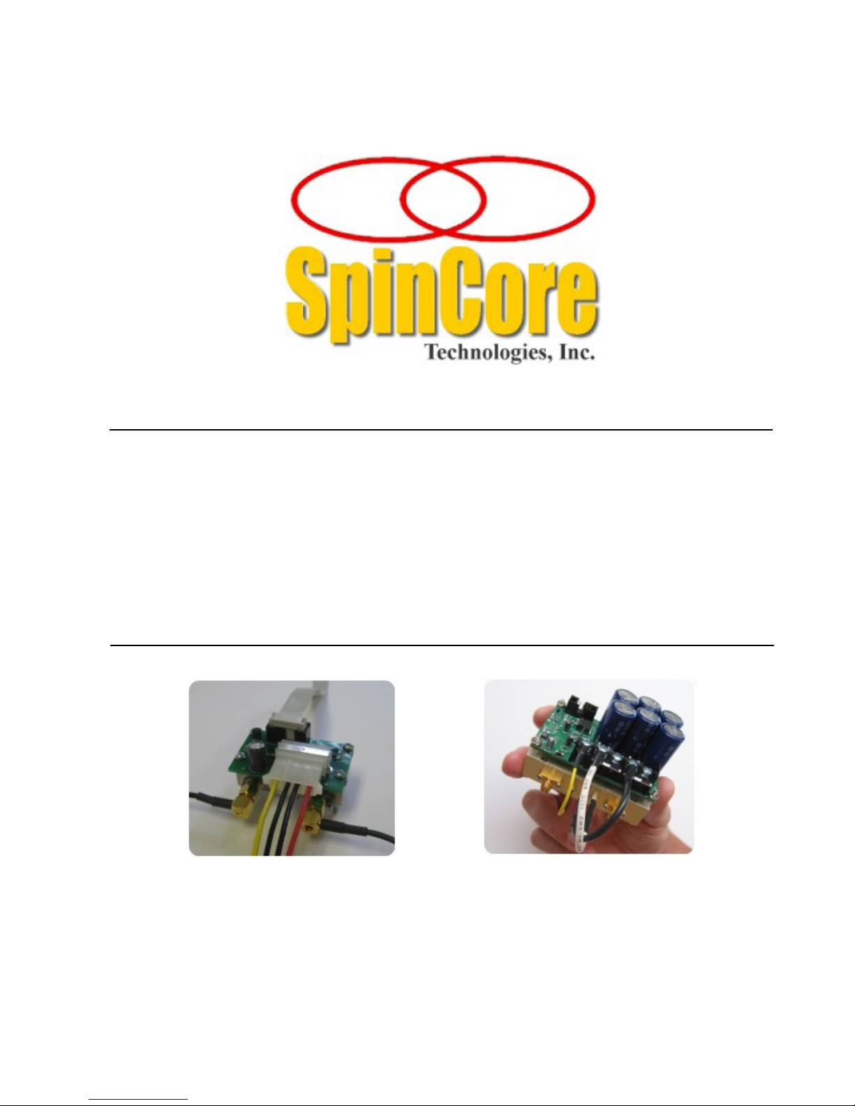
The PA10W RF power amplifier comes in a very compact broadband module delivering 10 Watts
RMS (20 Watts PEP, Peak Envelope Power into a 50-ohm load. It has a 3 dB range of 10 MHz to
75 MHz and is powered by a DC +12 V power supply (with the negative terminal grounded . The
PA10W has standard female SMA jacks for RF input and output, and a standard 4-pin ATX
connector for the input DC power. The PA10W typically operates in Class AB.
The product comes with blanking circuitry – the blanking circuitry keeps the PA10W blanked
(turned off until a TTL input (logical high is applied. The blanking circuitry helps to conserve
power, keeps the amplifier cool under typical operating conditions, and provides noise reduction
during the reception of NMR signals. To deblank the power amplifier, a TTL pulse needs to be
applied to the control circuitry.
The PA10W module measures 2.25" x 1.4" x 1.4" (57 x 36 x 36 mm . There are multiple
ordering options available, such as enclosures with integrated AC power supplies and enclosures
with a complete RF front-end with preamplifiers and filters for a complete mobile NMR, NQR and
MRI system. See the “Configuration Options” section later in this document for more information.
The use of a low pass (or band pass filter at the output of the PA10W is recommended to reduce
high frequency noise and improve performance.
2. Electrical Specifications
Parameter
Specification
Units
DC Input Voltage
12
V (DC
Max RF input power
50
mW
Max. continuous RF output power
10
W (RMS
Table 1: Basic electrical specifications for the PA10W power amplifier module.
http://www.spincore.com 6 2010-07-30
RF Power Amplifiers
3. Connector Information
RF Input and Output Connectors
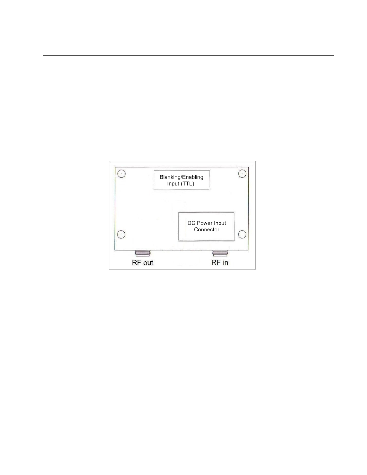
A top view of the PA10W module depicting RF input and output connectors is shown below in
Figure 1. When connecting the PA10W power amplifier, the RF signal source should be connected
to the SMA jack on the right hand side (top view of the circuit (RF in . The SMA jack on the left
hand side (top view is the RF output from the power amplifier (RF out .
Figure 1: Diagram of power amplifier RF connectors (top view . RF out and RF in are SMA
jack connectors.
TT Control Input Connector
The PA10W power amplifier module has a 10-pin shrouded male IDC connector, also shown in
Figure 1 above, which supplies the input TTL control signal. The control signal is pin 8 on the IDC
header and the corresponding ground is pin 7. The input is terminated by a 100-ohm load and
requires an external TTL signal source capable of sourcing at least 10 mA. A logical high signal is
required to deblank (enable the PA10W. The deblanking bit must be set at least 3 ms prior to
sending the RF signal or optimal power will not be achieved.
http://www.spincore.com 7 2010-07-30
RF Out
RF Power Amplifiers
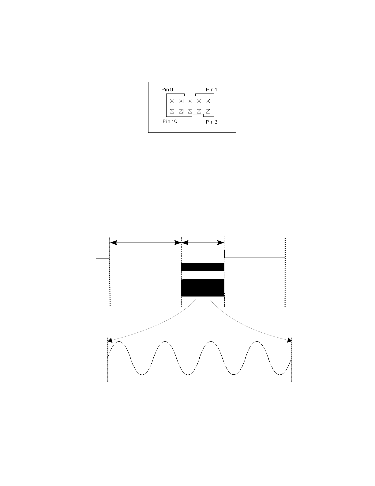
Note: The deblanking TTL input header is denoted P2 on the circuit board. Please see Figure 2
below, for pin diagram.
Figure 2: 10-pin IDC connector (Digi-Key part A33159-ND . Mates with Digi-Key part
HKC10H-ND or similar.
The timing diagram of a typical application of PA10W with the deblanking pulse applied prior to the
RF pulse is presented in Figure 3, below. When working with short RF pulses, on the order of 1 us
or so, triggering the oscilloscope on the falling edge of the deblanking pulse will help identifying and
capturing the RF pulse on the scope.
Figure 3: Representation of the deblanking and RF input and output signals to the PA10W.
The PA10W requires at least 3.0 ms of deblanking time prior to the RF pulse for full output power.
http://www.spincore.com 8 2010-07-30
Deblanking
Signal
RF Output
Deblanking Delay Pulse Time
RF Input
RF Power Amplifiers
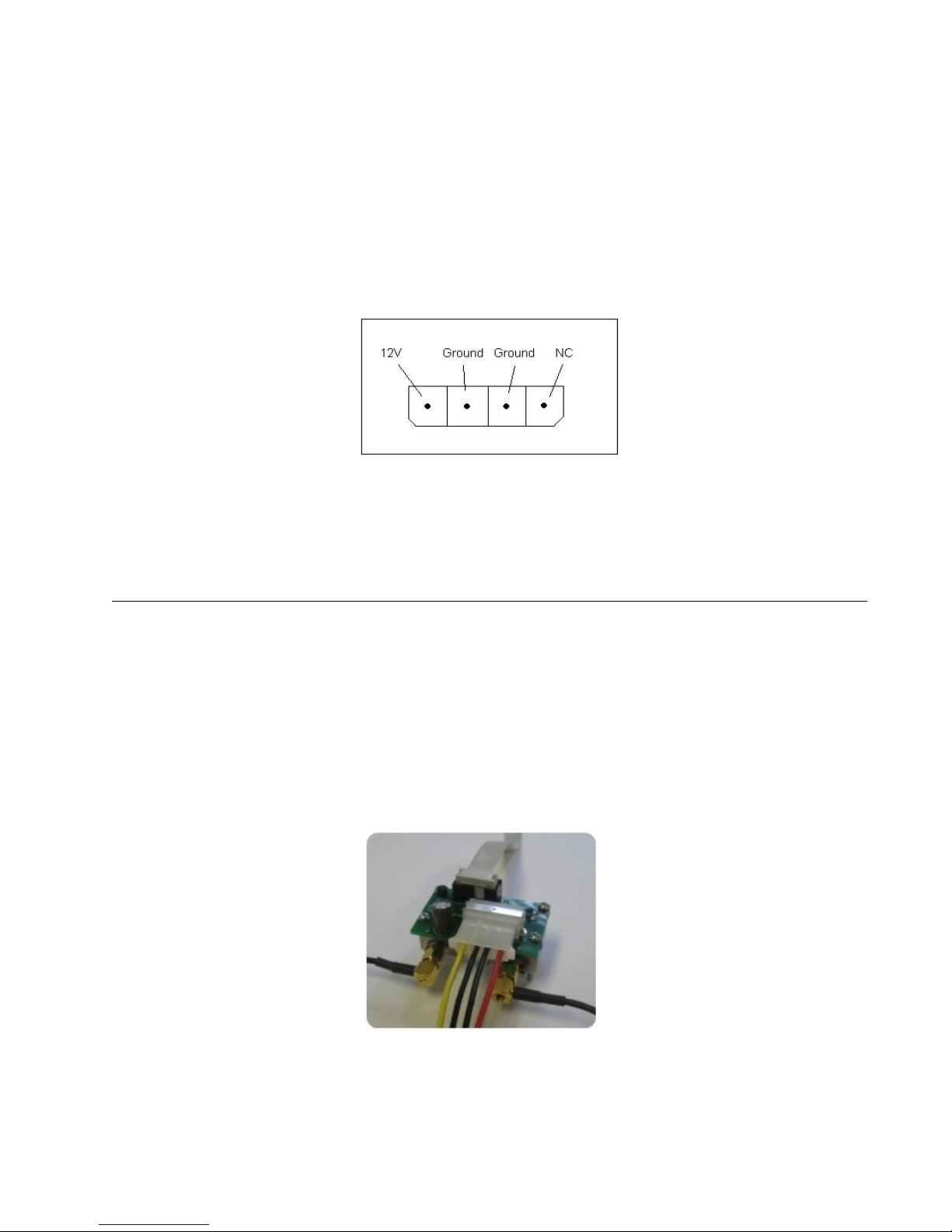
DC Power Input Connector
The PA10W RF power amplifier has a 4-pin input power connector. The input is for use with a
standard PC ATX power supply connector. The pin arrangements for this connector are shown
below in Figure 4.
Figure 4: 4-Pin input connector (Molex part 0531090410 . Mates with standard PC
power supply connector or Molex part 0015244048.
4. Configuration Options
Multiple configurations are available when ordering the PA10W RF power amplifier unit.
1. PA10W RF Module with deblanking circuitry, no enclosure
This configuration shown in Figure 5 does not have an enclosure and includes the switching
circuitry mounted on top of the power amplifier to enable it when a TTL pulse is applied to the input
pin. This feature reduces power consumption and keeps the power amplifier cool.
Figure 5: PA10W RF power amplifier – no enclosure.
http://www.spincore.com 9 2010-07-30
RF Power Amplifiers
2. PA10W RF module with enclosure
The PA10W RF power amplifier can be delivered in various external enclosures which protect
the RF power amplifier circuitry and include an AC/DC power supply, internal RF cables and output
low-pass (or band-pass filter (please specify your operating frequency at the time of purchase .
The power input is 90-264 V AC, the RF input/output signals are provided on external BNC
connectors, and the TTL inputs are routed through female DB-9 input connectors. The active TTL
signal needs to be connected to pin 4, with the corresponding ground line connected to pin 8.
Three standard enclosure configurations are available:
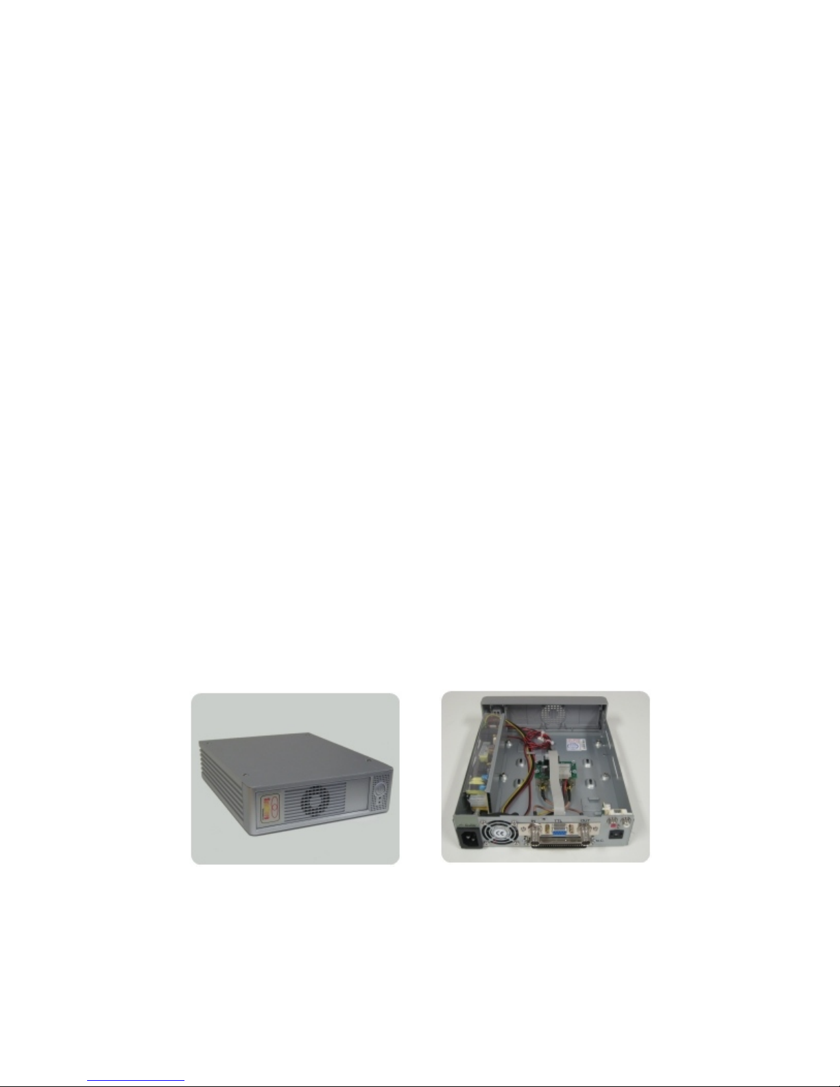
i) PA10W in a single bay enclosure (Figure 6)
Single bay enclosure additional specifications include:
-Excellent EMI/RFI shielding meets FCC & CE regulations.
-Built-in 4x4 cm quiet cooling fan.
-High quality 50 Watt AC input switching power supply.
-Dimensions are approximately 10.25” x 7.75” x 2.25” (26 x 19.5 x 6 cm .
Figure 6: PA10W RF power amplifier – single bay enclosure.
http://www.spincore.com 10 2010-07-30
Autres manuels pour PA10W
1
Ce manuel convient aux modèles suivants
1
Table des matières
Autres manuels SpinCore Technologies Amplificateur


