Installation and Instruction Manual - Series 230 Page 3 118128-001 Rev A
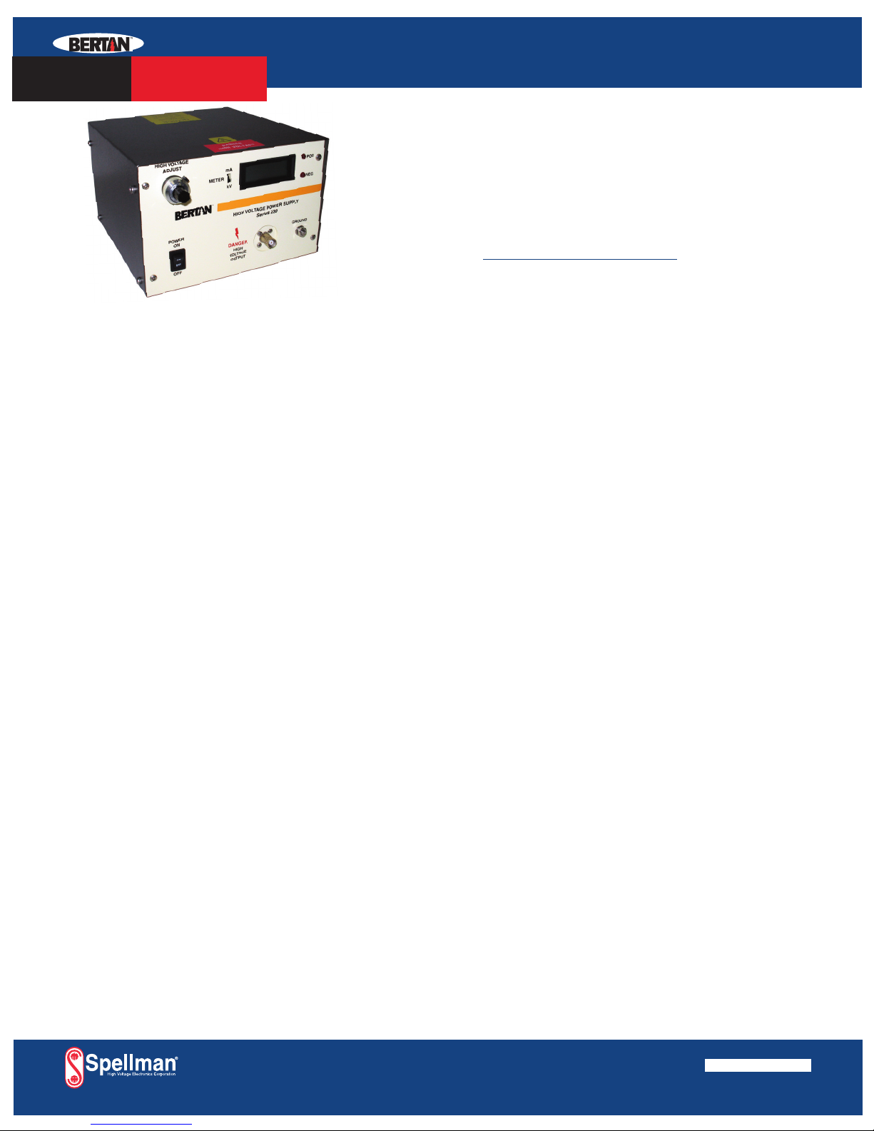
A continuous multi-turn digital dial is used to
adjust the high voltage output. The resolution
0.2% of maximum.
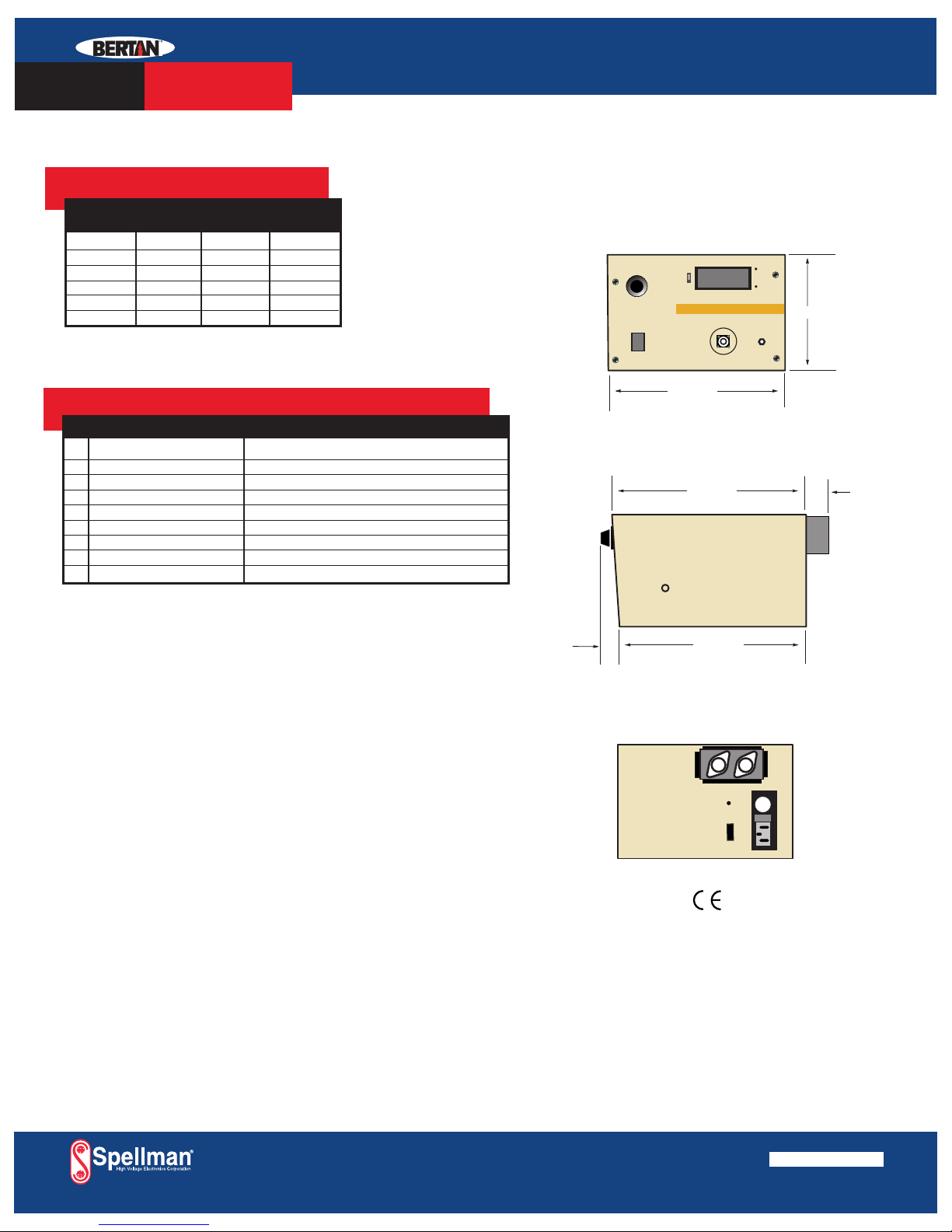
2.3 REAR PANEL CONTROLS,
CONNECTORS, AND TERMINALS
Gnd:
Ground is connected to the case of the Series
230.
Fuse:
The fuse is the ac line power fuse. It is rated for
1A, 250Vac for 105Vac-125Vac operation and
0.5A, and 250Vac for 210Vac-250Vac
operation. Should a fuse ever need replacement,
only these values should be used unless
otherwise advised by a qualified BERTAN
service technician.
Line Voltage Selector:
The line voltage selector selects the appropriate
line voltage 105Vac-125Vac or 210Vac-250Vac
at 50-60 Hz. By default, power supplies are
shipped from the factory in the 105-125V
position. Before energizing your power supply,
verify that the line voltage selector switch is in
the proper position for your mains input.
AC Line Plug:
The IEC 320 line plug receptacle accepts a
three-wire female line plug for ac line power.
WARNING! This unit is equipped with a
three-wire grounded line cord. This must be
used with a three-wire receptacle where the
"third wire" is connected to earth ground;
otherwise personal injury or death may occur.
2.4 POLARITY REVERSING:
WARNING! Before attempting to reverse the
power supply’s polarity, the power supply must
be turned off and the output fully discharged.
Failure to follow these procedures may result
in damage to the power supply, associated test
equipment and/or personnel.
For 1kV to 5kV output models, a screwdriver-
adjustable POLARITY SELECTOR SWITCH is
accessible at the rear panel of the unit, next to
the HV output connector. For 10kV to 50kV
output models, the polarity of the HV output is
reversible by means of an internal switching
mechanism that is easily accessible upon
removal of the top cover. The polarity reversal
module is a clear plastic assembly identified by
the exiting silicone high voltage cables. It is a
two-part assembly. To change the polarity, turn
off power supply, remove all cover screws
holding the top cover on and:
a. Remove the two diagonally opposed screws
fastening the top portion of the module
assembly to the bottom portion. NOTE: DO
NOT DESOLDER WIRES OR PINS.
b. Carefully separate the module by pulling
the top portion from the bottom portion.
The module portions are fitted very snugly
and removal may be eased by slightly
rocking the assembly.
c. Rotate the top portion of the module
assembly 180q, taking care not to unduly
stress the high voltage cables.
d. Rejoin the 2 portions of the module
assembly. Make sure that the top portion is
entirely seated to the bottom portion.
NOTE: An interlock automatically insures
that the high voltage cannot be applied until
the portions of the module are properly
mated.
e. Resecure the top portion to the bottom
portion of the Polarity Reversal Module
Assembly.
f. Re-cover the power supply.
2.5 PREPARATION FOR USE
WARNING! Before energizing your power
supply, thoroughly review and follow these
procedures. Failure to do so may result in
damage to equipment and injury or death to
personnel.
To prepare the Series 230 for use, use the
following procedure:
Set the Series 230 for the appropriate line
voltage as specified in Section 2.3.
Connect a ground strap from case ground (on the
rear panel) to a system common.
Select the appropriate HV output polarity for the
application.