Speedsignal B-360DB06 Manuel utilisateur

B-360DB06_R1 20.02.2023 Seite 1 von 25
EINBAUANLEITUNG
INSTALLATION GUIDE
B-360DB06 Mercedes 10,25”
LARDIS:ONE DS
1920
720
Für Fahrzeuge mit oder ohne SPV-Eingang
For vehicles with or without SPV input
Einzel-Display Single Display
10R – 020339 für 3670033

B-360DB06_R1 20.02.2023 Seite 2 von 25
Fahrzeuge Vehicles
Mercedes
Infotainmentsystem
MBUX NTG 6
Ausstattungscode bei Sprinter:
Equipment code for Sprinter:
CODE E4M
Der DisplaySwitch funktioniert nur für
Fahrzeuge, die das genannte
Infotainmentsystem haben.
The DisplaySwitch works only for vehicles
that have the mentioned infotainment
system.
Display
Auflösung Resolution
1920*720
Diagonale Diagonal
10,25“ = 26 cm
A W177 (2018-)
B W247 (12/2018-)
CLA Baureihe 118 (2019-)
GLA H247 (2020-)
GLB X247 (2019-)
GLE V167 (2018-)
Sprinter III W907, W910 (2018-)

B-360DB06_R1 20.02.2023 Seite 3 von 25
Lieferumfang Scope of delivery
DisplaySwitch Set Mercedes 10,25“
DisplaySwitch Set Mercedes 10,25“
Powermanagement Set Mercedes
Powermanagement Set Mercedes
Mono-Verstärker Set
Mono Amplifier Set
Bordrechner Set Mercedes 10,25”
On-board computer set Mercedes 10,25”
3676315
356ASRGN1911
369DB01-02
Ohne Artikelnummer
Without article number
C-3670079
3630108
C-3674727-USB27
356ASRGN1909
3670033
C-3670033
3910030-02
3911137
Ohne Artikelnummer
Without article number
3630104
3630105
3630107
C-3676317
3630098
C-3674727-USB60
B-360DB06_R1 20.02.2023 Seite 4 von 25
Einbau Part 1: DisplaySwitch Installation part 1: DisplaySwitch
1. Ausbau Headunit (Fundort fahrzeugabhängig)
2. Plug&Play Anschluss der Kabelsätze
3. Anschluss der Interfaces an Kabelsatz
4. Installation des Tasters
5. 5m USB-Verlängerungskabel und 5m DVI auf HDMI Kabel in den Kofferraum verlegen
1. removal of headunit (location depends on vehicle)
2. plug&play connection of the cable sets
3. connection of the interfaces to the cable set
4. installation of the button
5. Install 5m USB extension cable and 5m DVI to HDMI cable in the trunk

B-360DB06_R1 20.02.2023 Seite 5 von 25
Im Lieferumfang ist ein Fakra-Kabelset enthalten, welches vor Beginn des Einbaus entsprechend zusammengesteckt werden muss.
Im Folgenden wird dies gezeigt.
The scope of delivery includes a Fakra cable set, which must be plugged together accordingly before starting the installation. This is shown below.
Fakra-Kabel 3630098 Fakra cable 3630098
D
B
C
A
E
C
A
Die übrig gebliebenen Kabel bzw. Stecker sind für den weiteren Einbau irrelevant.
The remaining cables or connectors are irrelevant for further installation.
B
A
B
Variante 1
Benötigt bei Einbau S.8, S.9, S.11
Variant 1
Required for installation p.8, p.9, p.11
Variante 2
Benötigt bei Einbau S.7
Variant 2
Required for installation p.7

B-360DB06_R1 20.02.2023 Seite 6 von 25
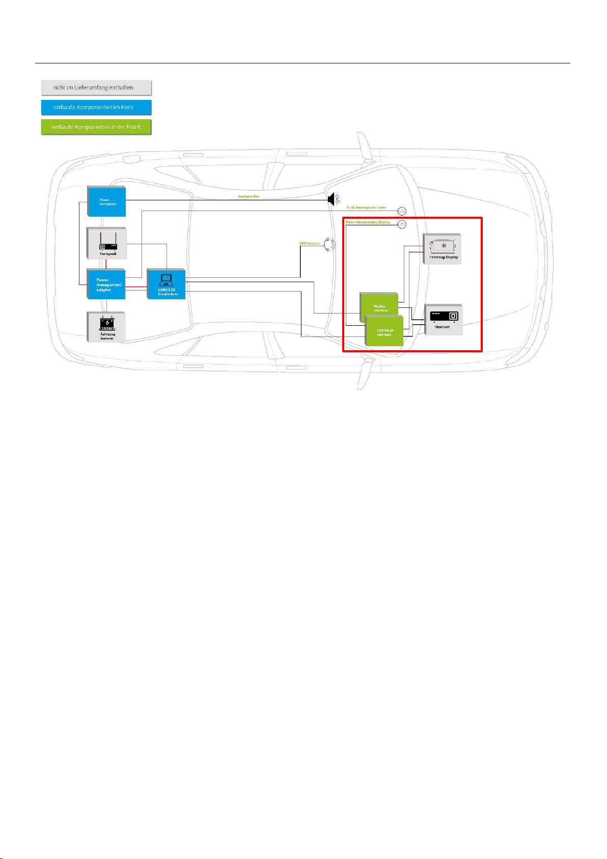
Fahrzeug mit Einzel-Display: Einbau hinter dem Display Seite 7
Fahrzeug mit Einzel-Display: Einbau hinter der Headunit Seite 8
Fahrzeug mit Doppel-Display: Einbau hinter dem Display Seite 9-10
Fahrzeug mit Doppel-Display: Einbau hinter der Headunit Seite 11-12
Allgemeines für alle Einbau-Varianten Seite 13-14
Vehicle with single display: Installation behind the display Page 7
Vehicle with single display: Installation behind the headunit Page 8
Vehicle with double display: Installation behind the display Page 9-10
Vehicle with double display: Installation behind the headunit Page 11-12
General information for all installation variants Page 13-14
Übersicht Einbau Installation overview
B-360DB06_R1 20.02.2023 Seite 7 von 25
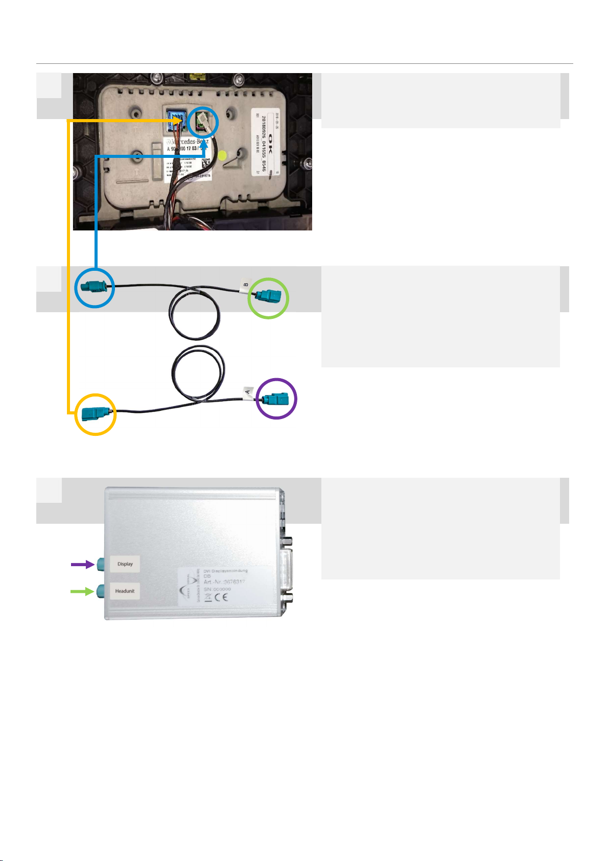
Blau markierten Stecker (1) an den Steckplatz des zuvor
ausgesteckten Stecker der Headunit anschließen. Orange
markierten Stecker (2) an zuvor abgesteckten Stecker an-
stecken.
Connect the plug marked in blue (1) to the slot of the previously
unplugged plug of the head unit. Connect the plug marked in or-
ange (2) to the previously unplugged plug.
Einbau hinter Display für Einzel-Display Installation behind display for single display
Display ausbauen und markierten, grünen Stecker abste-
cken.
Remove display and disconnect marked green connector.
1
2
Lila markierten Stecker „A“ am Interface 3676315 am Ein-
gang „Display“ anstecken.
Grün markierten Stecker „B“ am Eingang „Headunit“ anste-
cken.
Connect the connector "A" marked in purple to the "Display" input
on interface 3676315.
Connect the plug marked green "B" to the "Headunit" input.
3
1
B
2
A
A
B

B-360DB06_R1 20.02.2023 Seite 8 von 25
Blau markierten Stecker (1) an den Steckplatz des zuvor
ausgesteckten Stecker der Headunit anschließen. Orange
markierten Stecker (2) an zuvor abgesteckten Stecker an-
stecken.
Connect the plug marked in blue (1) to the slot of the previously
unplugged plug of the head unit. Connect the plug marked in or-
ange (2) to the previously unplugged plug.
Einbau hinter Headunit für Einzel-Display Installation behind headunit for single display
Headunit ausbauen. Hinter der Headunit befindet sich ein
grüner Doppel-Fakra-Stecker. Diesen abstecken.
Remove the head unit. Behind the headunit there is a green dou-
ble fakra connector. Disconnect it.
1
2
Lila markierten Stecker „A“ am Interface 3676315 am Ein-
gang „Headunit“ anstecken.
Grün markierten Stecker „B“ am Eingang „Display“ anste-
cken.
Connect the connector "A" marked in purple to the "Headunit" in-
put on interface 3676315.
Connect the plug marked green "B" to the "Display" input.
3
1
B
2
A
A
B

B-360DB06_R1 20.02.2023 Seite 9 von 25
Nun muss der Kabelsatz angesteckt werden. Blau markier-
ter Stecker (1) am Steckplatz des grünen Eingangs anste-
cken. Grün markierter Stecker (3) am fahrzeugseitigen, zu-
vor abgesteckten grünen Stecker anstecken.
Now the cable set must be plugged in. Plug the blue-marked con-
nector (1) into the green input slot. Plug the plug (3) marked
green into the green plug on the vehicle side that was previously
unplugged.
Einbau hinter Display für Doppel-Display Installation behind display for double display
Display ausbauen und nach vorne klappen. Dafür muss zu-
erst die, mit dem Pfeil markierte, Plastikabdeckung ober-
halb des Displays entfernt und anschließend zwei Schrau-
ben entfernt werden.
Remove the display and fold it forwards. First remove the plastic
cover above the display marked with the arrow and then remove
two screws.
1
3
Nun den orange markierten Stecker (4) am Display-Inter-
face 3676315 am Eingang „Display“ anstecken. Anschlie-
ßend den violett markierten Stecker (5) am Display-Inter-
face 3676315 am Eingang „Headunit“ anstecken.
Now connect the plug marked orange (4) to the "Display" input on
the display interface 3676315. Then connect the connector (5)
marked in violet to the "Headunit" input on the display interface
3676315.
4
1
3
4
5
4
5
Markierten, grünen Stecker abstecken.
Disconnect the marked green plug.
2

B-360DB06_R1 20.02.2023 Seite 10 von 25
Schwarzen Stecker vom markierten Steckplatz der
Headunit abstecken, Gehäuse herausziehen. Hier wird
Masse und +12V abgegriffen.
Disconnect the black plug from the marked slot of the headunit,
pull out the housing. Ground and +12V are tapped here.
5
+12V: Pin 14, rot-grau red-grey
Masse Ground: Pin 1, braun brown
6
Table des matières
Autres manuels Speedsignal Système vidéo embarqué


