-4-
It is important that you read this manual very carefully and follow it for your installation carefully.
Before you start your installation, please consider following concerns.
1. Disconnect the negative (-) battery cable before mounting the amplifier or making any connections.
Check the battery and alternator ground (-) connections. Make sure they are properly connected
and free of corrosion.
2. Before selecting a mounting location for amplifier, please take some concerns into consideration
with cooling efficiency and safety.
This amplifier uses heavy-duty and good heat radiation heatsink design for avoiding excess heatsink
from amplifier circuitry. But for better heat radiation performance, it is good to find the mounting
location where you can install amplifier vertically with the heatsink fins and better air flow around
amplifier. For the safety, you have to find fry and well ventilated location and make sure any wires
cables and car equipment are not interfaced with amplifier installation. Be sure the mounting location
and drilling of pilot ables for mounting will not present a hazard to any wires, control cables, fuel lines,
fuel tanks, hydraulic ines or other vehicle systems or components.
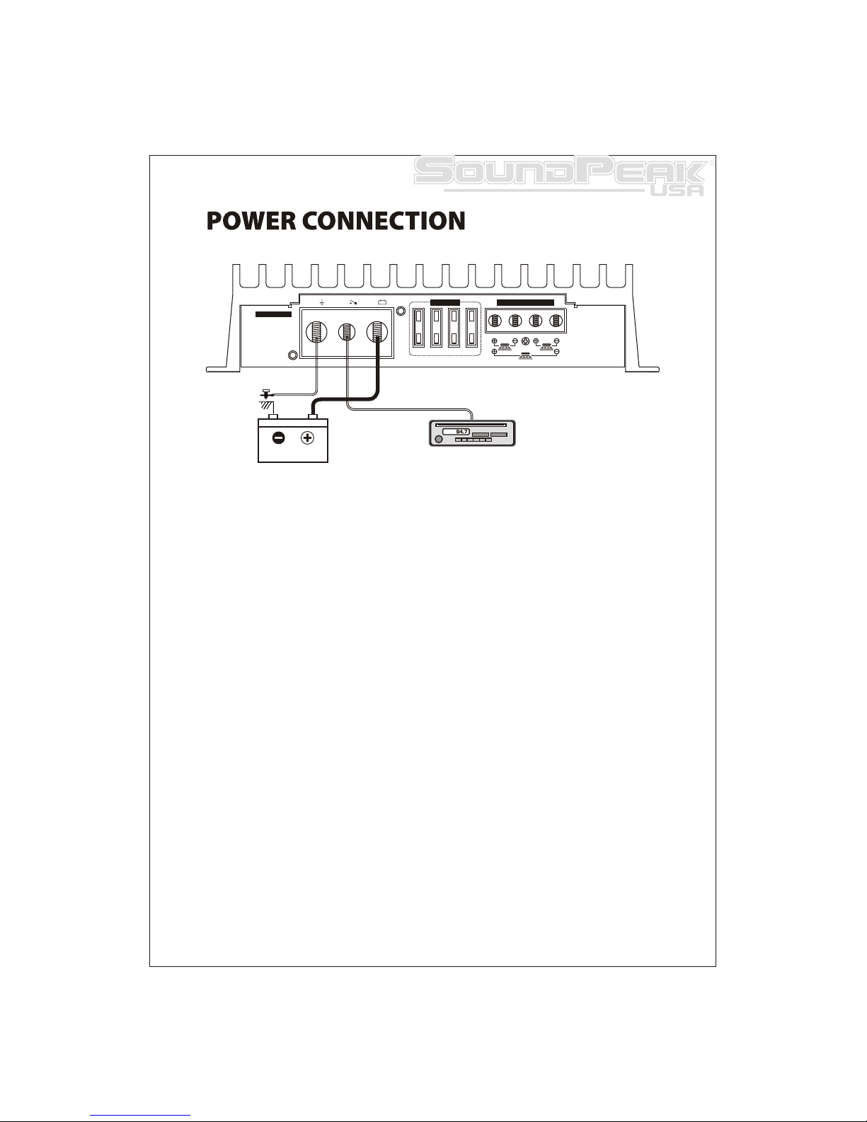
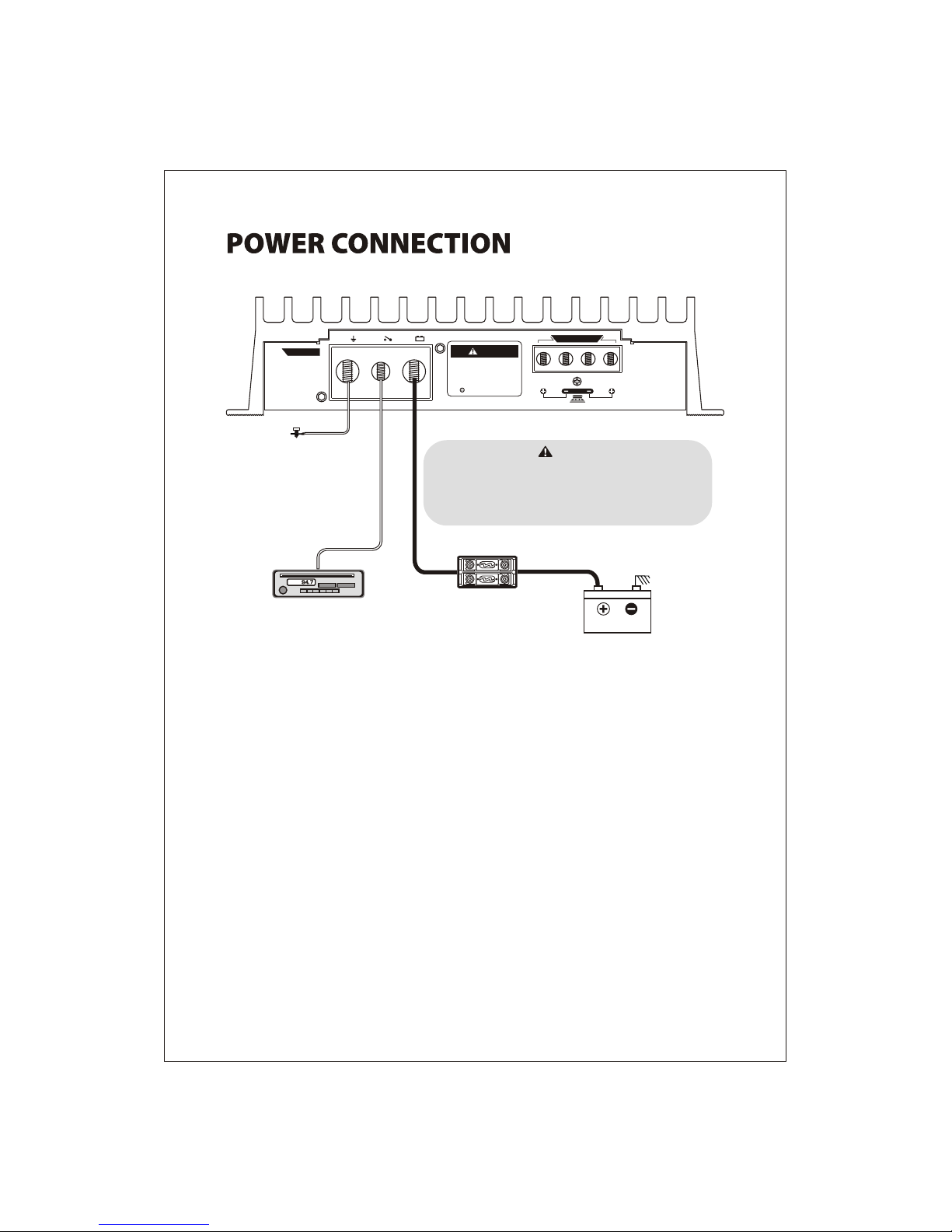
3. Power connection
Before installing amplifier, disconnect the negative(-) wire from battery to protect any accidental
damage to your amplifier and system. Connection one end of fuse holder to the power cable and
the other end of fuse holder to positive battery within 20cm of the same cable. Connect the power
cable to the amplifier power terminal labeled as +12V. This fuse location will protect the system and
the vehicle against the possibility of a short circuit in the power cable. Be sure to use a fuse and fuse
holder adequate for the application. No fuse is required before the amplifier power connection.
4 Ground connection
Locate a secure grounding connection as close to the amplifier as possible. Make sure the location is
clean and provides a direct electrical connection to the frame of the vehicle. Connect one end of a
short piece of the same size cables as the power cable to the grounding point. Run the other end of
the cable to the amplifier mounting location.
Connectiot the ground cable to the screw terminal labeled as GND.
5. Remote connection
Run a remote turn on cable from the switched +12V source you will be using to turn on the system
components. This may be a toggle switch, a relay, or your source unit's remote trigger wire, or power
antenna trigger wire. Connect the remote turn on cable to the power terminal labeled as REM.
Run this lead to the amplifier mounting location. Using 16AWG wire or larger.
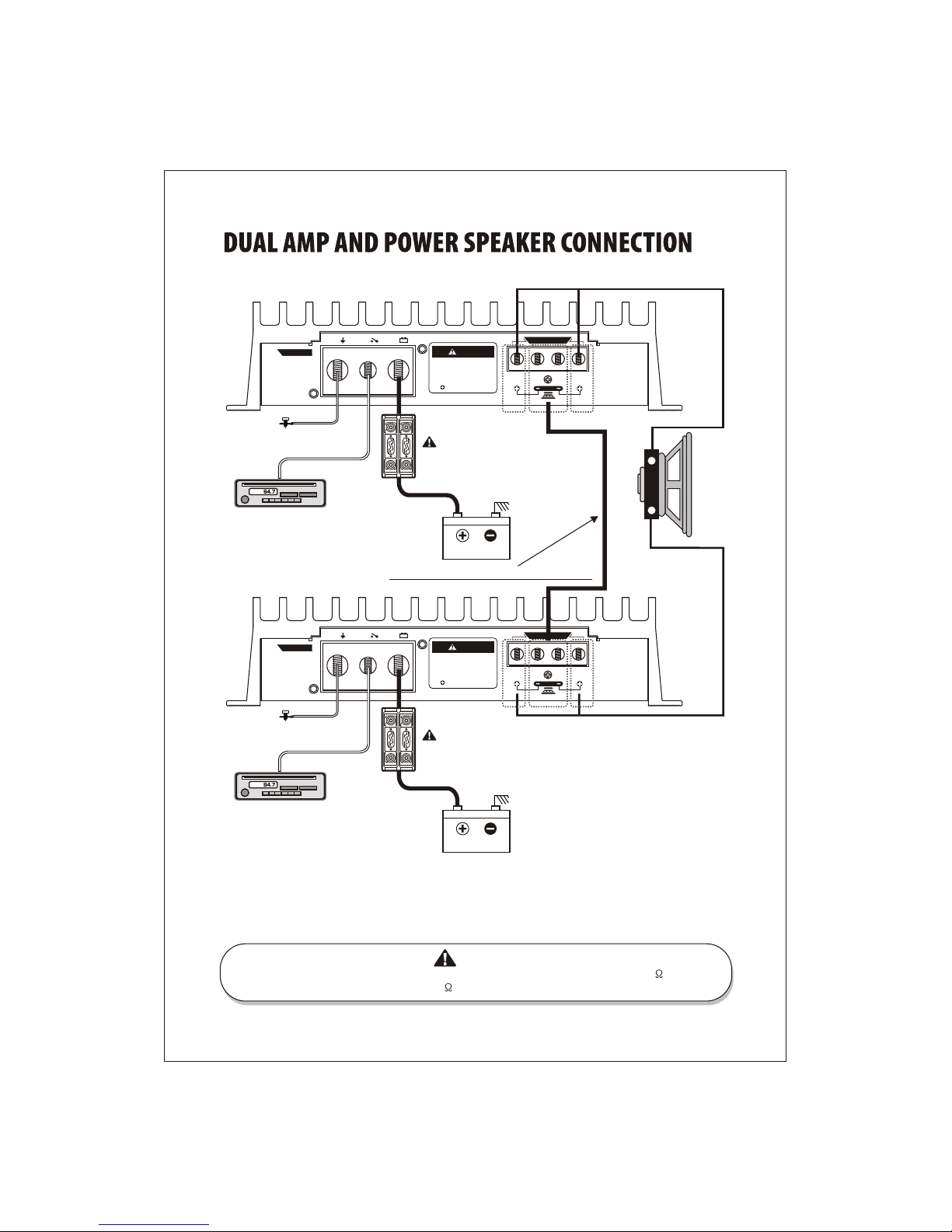
BATTERY HEAD UNIT
to REMOTE Turn-on
from HEAD UNIT
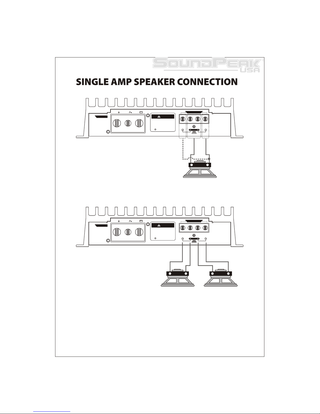
GROUND
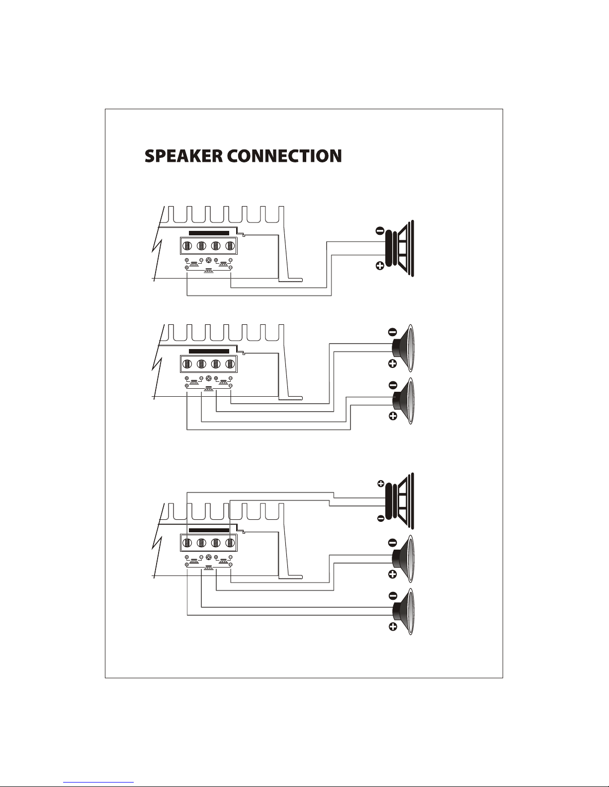
FUSE SPEAKER OUTPUT
POWER
GND REM B+
CH1 CH 2
BRIDGE
[SP-1200.2 dbPRO]