SoundMax SM-CCR4705 Manuel utilisateur

SM-CCR4705
Мультимедийный ресивер 2 DIN с 7” сенсорным TFT-дисплеем
Руководство по эксплуатации
2 DIN Multimedia receiver with 7” TFT touch screen display
Instruction manual
TF USB
BAND
MODE

2
Dear customer!
Thank you for purchasing our product. For safety, it is strongly recommended to read this manual carefully
before connecting, operating and/or adjusting the product and keep the manual for reference in the future.
Important safeguards ............................................................................................................................................. 3
Accessories ............................................................................................................................................................. 4
Installation/Connections ........................................................................................................................................ 5
Panel controls ....................................................................................................................................................... 10
General operations ............................................................................................................................................... 13
Radio operations ................................................................................................................................................... 14
Bluetooth operations ........................................................................................................................................... 15
USB/SD operations ............................................................................................................................................... 17
Steering wheel control (SWC).............................................................................................................................. 21
Troubleshooting guide ......................................................................................................................................... 22
Specifications ........................................................................................................................................................ 23

3
Important safeguards
• Read carefully through the manual to familiarize yourself with this unit.
• Keep this manual handy as a reference for operating procedures and precautions. Do not allow persons who have not
read through this manual to use this unit.
• Do not allow this unit to come into contact with liquids. Electrical shock could result. Also, damage to this unit, smoke,
and overheating could result from contact with liquids or dust. Protect this unit from moisture.
• Make sure that foreign objects do not get inside the unit; they may cause malfunctions, or create safety hazards such
as electrical shock or laser beam exposure.
• The beginning of operation is the moment of the unit installation. Before use the device in winter it is recommended to
heat up the passenger compartment during 20 seconds or to the operation temperature.
• Using the unit with the temperature that goes beyond the operation temperature greatly decreases the operation
resource of the screen and other components of the unit and can result in an outage.
• Disconnect the vehicle’s negative battery terminal while mounting and connecting the unit.
• The unit is designed for negative terminal of the battery, which is connected to the vehicle metal. Please ensure it
before installation.
• When replacing the fuse, be sure to use one with an identical amperage rating. Using a fuse with a higher amperage
rating may cause serious damage to the unit.
• Do not allow the speaker wires to be shorted together when the unit is switched on. Otherwise it may overload or
burn out the power amplifier.
• Make sure you disconnect the power supply and aerial if you will not be using the system for a long period or during a
thunderstorm.
• Make sure you disconnect the power supply if the system appears to be working incorrectly, is making an unusual
sound, has a strange smell, has smoke emitting from it or liquids have got inside it. Let a qualified technician check the
system.
• Always keep the volume low enough so that you can hear sounds from outside the vehicle.
• Should this product fail to operate properly, contact your dealer or nearest service center.

4
Accessories
1 pc
1 pc
2 pcs
2 pcs
8 pcs
1 pc
1. Media player
2. Remote controller
3. ISO connector
4. Decorative plastic
frame
5. Mounting parts:
Mounting bracket
Screw
6. Instruction manual
1 pc
5
Installation/Connections
Choose the mounting location where the unit will not interfere with the normal driving function of the
driver.
Before finally installing the unit, connect the wiring and make sure that the unit works properly.
Consult with your nearest dealer if installation requires the drilling of holes or other modifications of the
vehicle.
Install the unit where it does not get in the driver's way and cannot injure the passenger if there is a
sudden stop, like an emergency stop.
If installation angle exceeds 30° from horizontal, the unit may not perform properly.
Avoid installing the unit where it would be subject to high temperature, such as from direct sunlight, or
from hot air, from the heater, or where it would be subject to dust, dirt or excessive vibration.

6
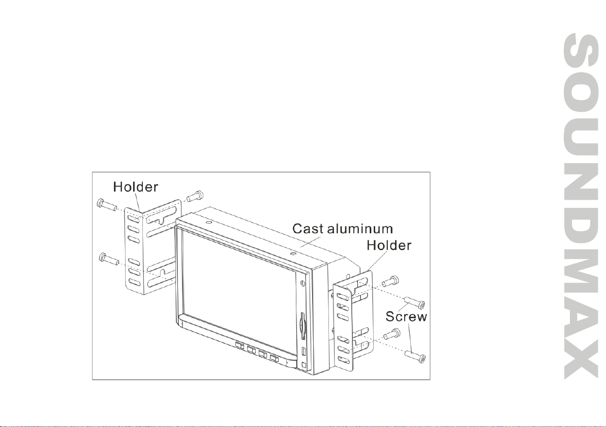
Mounting
• Connect the cable set and the antenna to the vehicle’s electronics corresponding to the connection table
(see further).
• Attach the mounting brackets to the sides of the unit, and fix them with supplied screws.
• Insert the unit into the slot until the stop. The unit then audibly snaps.
• Fasten the screws to fix the unit.
• The device is distinguished by a high degree of output. During operation, this results in a strong heat
generation. Therefore no cables or other parts may adjoin the device. If their insulation melts, there is the
risk of a short circuit or fire.
• Removing: Turn off the device. Clamp off the negative pole of the vehicle battery for the duration of the
disassembly. Unscrew the four screws. Remove carefully the unit from the slot and disconnect all wires. Make
sure that no vehicle cable can cause a short circuit after the device has been unplugged.
Connection diagram
7
1
2
15
16
A
3
4
5
6
7
8
9
10
11
12
13
14
12 3 4 5 B
12 3 4 5
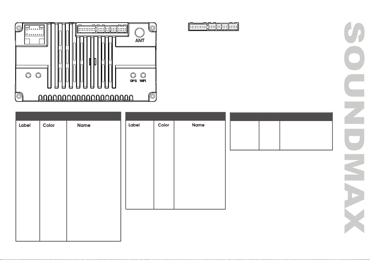
A--Power
B
1--RCA
2-- /
3--4P USB
4--6P USB
5--BRAKE/F-CAM
B
GND Black Ground wire
BATT+ Yellow Battery wire
ACC Red lgnition wire
ILLUMI Orange Lamp control wire
BACK Pink Reverse wire
KEY-1 Orange/Black Steering wheel control wire 1
ANT.POW
Blue Automatic antenna
FR- Gray/Black Front right speaker -
FR+ Gray Front right speaker +
RL- Green/Black Rear left spearker -
RL+ Green Rear left spearker +
FL- White/Black Front left spearker -
FL+ White Front left spearker +
RR- Purple/Black Rear right speaker -
RR+ Purple Rear right speaker +
KEY-2 Steering wheel control wire 2
Brown
A: Power B:5
CAMERA Yelloww Reverse camera input
Yelloww Front camera input
F-CAM
BRAKE Yellow Brake control
F-CAM+12V Bluee Front camera power +12V
AUX VIDEO Yellow Video input
B:1
VIDEO OUT00 Yellow Video output0
VIDEO OUT11 Yellow Video output1
AUX AL White Left audio input
RL White Rear left audio output
FL White Front left audio output
AUX AR Red Right audio input
RR Red Rear right audio output
FR Red Front right audio output
SUB Green Sub woofer output
MIC Black Microphone
PCON Pinkk External power amplifier
8
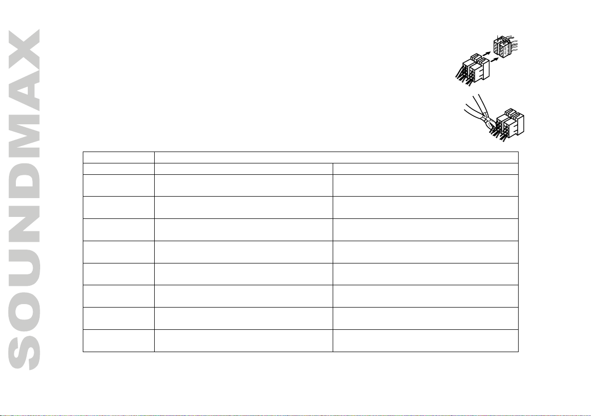
Using the ISO Connector
1. If your car is equipped with the ISO connector, then connect the ISO connectors
as illustrated.
2. For connections without the ISO connectors, check the wiring in the vehicle
carefully before connecting, incorrect connection may cause serious damage to
this unit.
Cut the connector, connect the colored leads of the power cord to the car battery as
shown in the colour code table below for speaker and power cable connections.
Location FUNCTION
Connector B Connector A
1 Rear right speaker (+)/Violet Parking sensor control wires / Pink
2 Rear right speaker (-)/Violet-Black Brake line / Brown
3 Front right speaker (+)/Gray Steering wheel control / Orange-Black
4 Front right speaker (-)/Gray-Black Battery 12V (+)/Yellow
5 Front left speaker (+)/White Power antenna/Amplifier / Blue
6 Front left speaker (-)/White-Black Panel light / Orange
7 Rear left speaker (+)/Green ACC+/Red
8 Rear left speaker (-)/Green-Black Ground/Black
Power antenna wire is intended for power supply of the antenna and for remote control of an additional
amplifier.
9
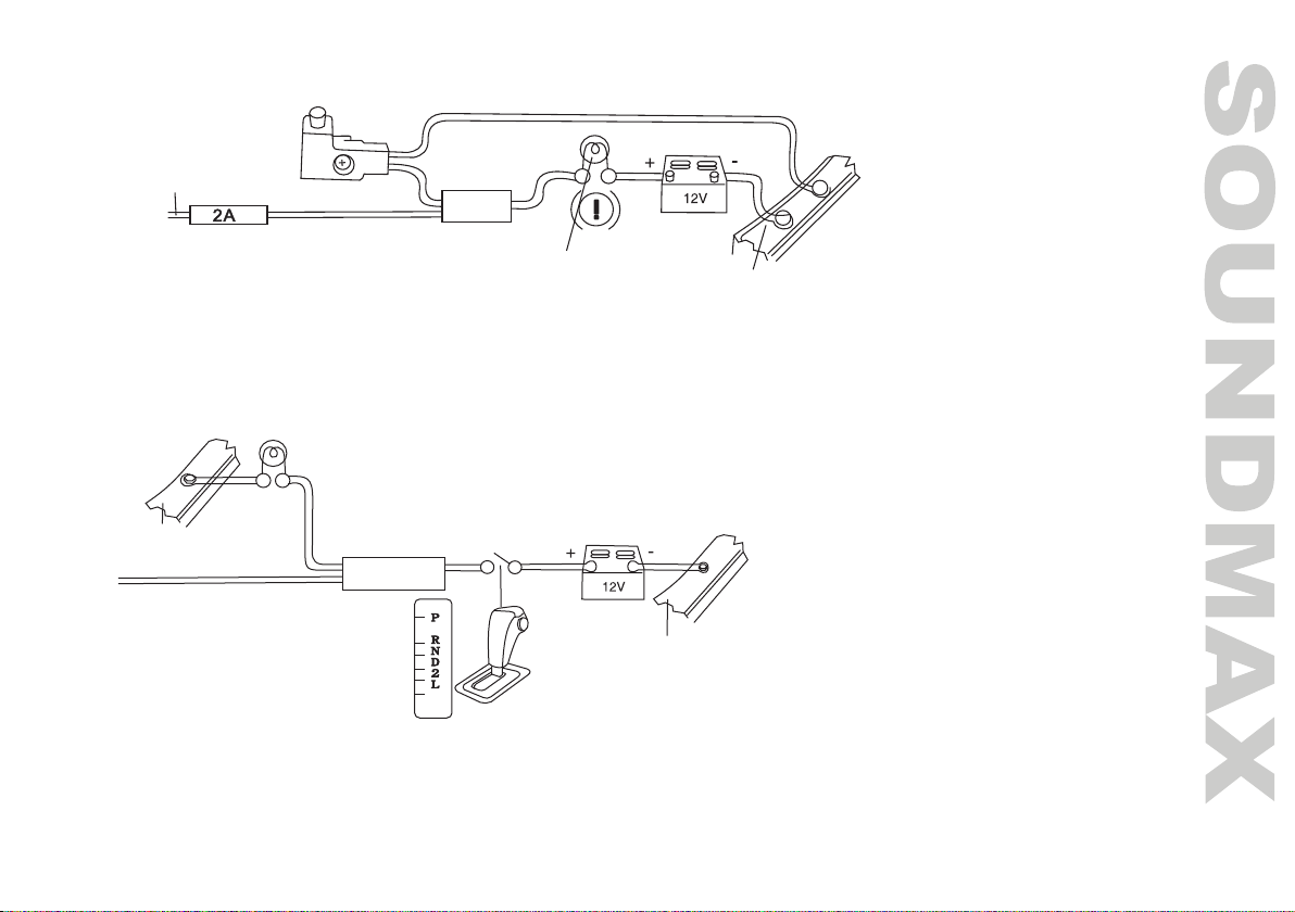
Parking wire connection
If Parking cable is connected to hand brake switch, the video display of the TFT monitor will be controlled by driving
status, system setup and input video sources. When the car is moving ahead, if the video is played, the screen
shows a warning message. The warning screen will prevent the driver from watching images.
Reverse driving cable connection
If the rear view video camera is connected, the unit automatically switches to camera picture during reverse driving. The
unit returns to the original work mode after the reverse driving is done.
Car frame
Brake light lamp
Battery
Parking brake line
Car frame
Car frame
Battery
Reverse driving light
Pink wire
Gearbox
10
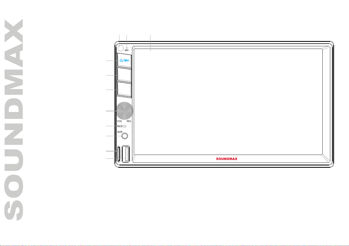
Panel controls
1. Display
2. Microphone
3. IR sensor
4. POWER button/
MUTE button
5. MODE button
6. BAND button
7. Volume/Select
knob
8. Reset button (hole)
9. AUX input
10. TF card slot
11. USB port
TF USB
BAND
MODE
1
4
5
6
7
8
9
10
11
23
Table des matières
Langues :
Autres manuels SoundMax Récepteur

SoundMax
SoundMax SM-CMD3008 Manuel utilisateur

SoundMax
SoundMax SM-RD2114UB Manuel utilisateur

SoundMax
SoundMax SM-RD2123UB Manuel utilisateur

SoundMax
SoundMax SM-CDM1058 Manuel utilisateur

SoundMax
SoundMax SM-CMD5003G Manuel utilisateur

SoundMax
SoundMax SM-CMD5003 Manuel utilisateur

SoundMax
SoundMax SM-CMD3015 Manuel utilisateur

SoundMax
SoundMax SM-2601 Manuel utilisateur

SoundMax
SoundMax SM-CMD3014 Manuel utilisateur

SoundMax
SoundMax SM-2604 Manuel utilisateur


