10
Amplifier Functions Funciones del amplificador
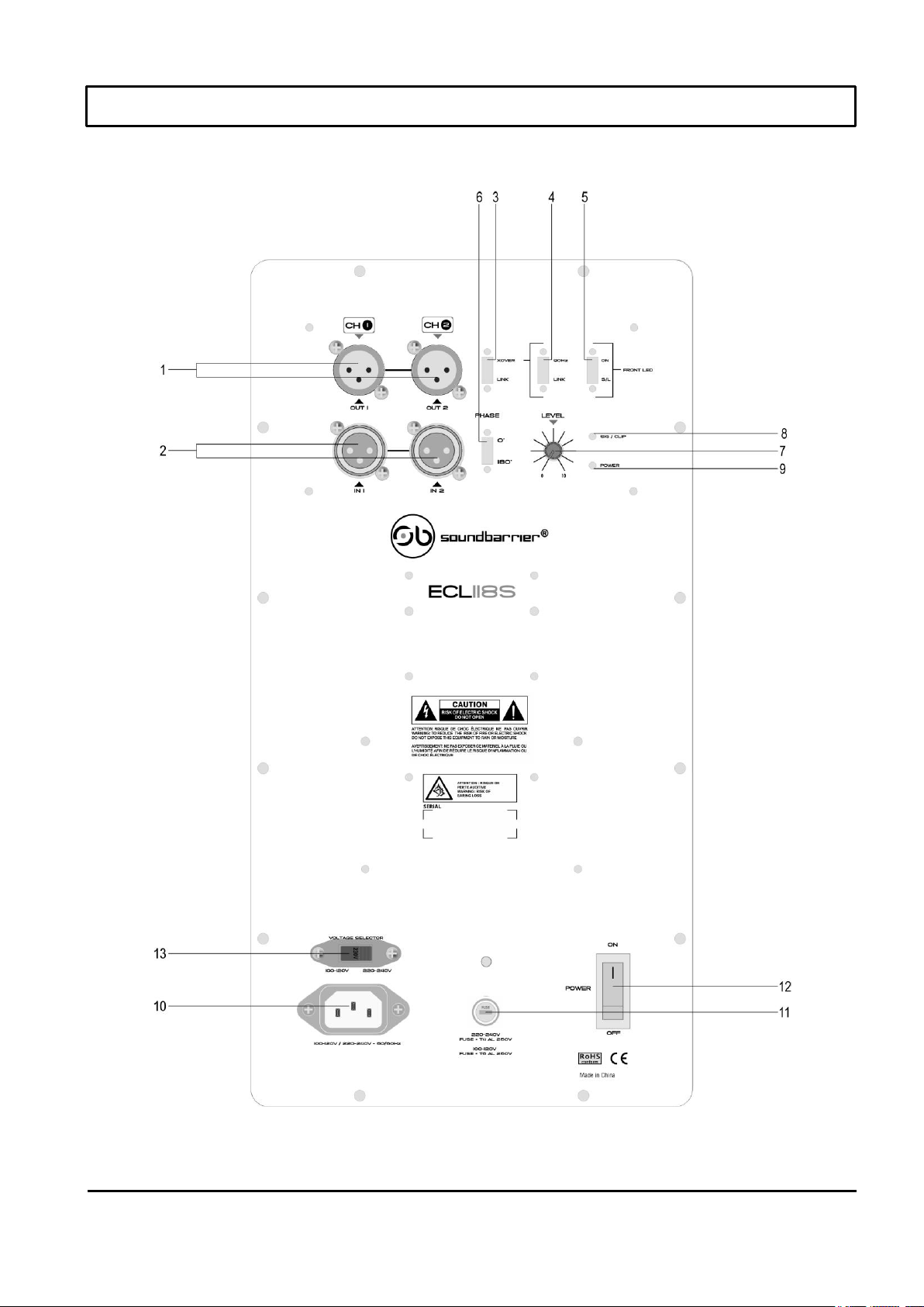
1. OUTPUTS 1 & 2
When set to CROSSOVER, the XLR jacks will send the
signal coming from the input through the built-in crossover.
You can also select the crossover frequency. The output
signal should then be used to play the filtered frequencies
with your standard full-range speakers. When set to LINK,
the crossover function is disabled.
2. INPUTS 1 & 2
Combination inputs are designed for either TRS and XLR
balanced plugs at line level either from a mixer or another
speaker. The source can either be stereo or mono.
3. Crossover Link Selection Switch
Switches between the internal CROSSOVER or the LINK
mode to send the inputs directly to the outputs.
4. Crossover Switch Selector
This switch will determine the crossover point where the high
pass filter will be set to output high-frequency content to the
outputs. The lower frequencies under the crossover point will
be played by the internal speaker in the subwoofer.
5. LED Defeat Switch:
The front-mounted LED has two functions. This switch
toggles between those functions.
ON position: Front-mounted LED indicates when power is
on.
S/L position: Front-mounted LED indicates when the limiter
is engaged. (If the LED turns red in this position, the speaker
is distorting.)
6. Phase Selection Switch:
The Phase switch lets you alter the polarity of the input signal.
When the Phase switch is in its default "O" setting, phase is
unaffected.
7. Level:
This knob affects the volume of the internal speaker.
8. Signal Indicator:
The SIG/CLIP LED will light up BLUE when the speaker is
receiving a signal. If it is distorting, the LED will turn RED,
and the MASTER VOLUME should be turned down.
9. Power LED:
The Power LED indicates that the speaker's AC power cord is
connected to an electrical outlet, and the Power Switch is turned
down.
10. IEC Power Input:
Plug in the IEC AC cable here.
11. Fuse Carrier
Main fuse Housing.
12. Power Switch
Turns the speaker off.
13. Voltage Selector
Ensure the Switch is set to the correct AC voltage before
connecting or powering 120V-60Hz / 240V-50Hz.
1. SALIDAS 1 Y 2
Cuando seestablece en CROSSOVER, los jacks XLR enviarán
la señal proveniente de la entrada a través del crossover
incorporado. También puede seleccionar la frecuencia de
cruce. La señal de salida debe usarse para reproducir las
frecuencias filtradas con sus altavoces estándar de rango
completo. Cuando se establece en LINK, la función de cruce
está desactivada.
2. ENTRADAS 1 y 2
Las entradas combinadas están diseñadas para conectores
balanceados TRS y XLR a nivel de línea, ya sea desde un
mezclador u otro altavoz. La fuente puede ser estéreo o mono
3. Interruptor de selección de enlace Crossover
Cambia entre el modo CROSSOVER o LINK interno para
enviar las entradas directamente a las salidas
4. Selector de interruptor de Crossover
Este interruptor determinará el punto de cruce donde se
establecerá el filtro de paso alto para enviar contenido de alta
frecuencia a las salidas. Las frecuencias más bajas debajo del
punto de cruce serán reproducidas por el altavoz interno del
subwoofer.
5. Interruptor de desactivación de LED:
El LED montado en la parte delantera tiene dos funciones.
Este interruptor alterna entre esas funciones.
Posición ON: El LED montado en la parte delantera indica
cuando está encendido.
Posición S/L: El LED montado en la parte delantera indica
cuando el limitador está activado. (Si el LED se vuelve rojo
en esta posición, el altavoz está distorsionando)
6. Interruptor de selección de fase:
El interruptor de fase le permite alterar la polaridad de la señal
de entrada. Cuando el interruptor de fase está en su
configuración predeterminada "O", la fase no se ve afectada.
7. Nivel:
Esta perilla afecta el volumen del altavoz interno.
8. Indicador de señal:
LED SIG/CLIP se iluminará en AZUL cuando el altavoz esté
recibiendo una señal. Si se está distorsionando, el LED se
volverá ROJO y el VOLUMEN MAESTRO se debe bajar
9. LED de encendido:
El LED de encendido indica que el cable de alimentación de
CA del altavoz está conectado a un tomacorriente y el
interruptor de encendido está apagado.
10. Entrada de alimentación IEC:
Enchufe el cable de CA IEC aquí
11. Portafusibles
Caja del fusible principal.
12. Interruptor de encendido
Apaga el altavoz.
13. Selector de voltaje
Asegúrese de que el interruptor esté configurado en el voltaje
de CA correcto antes de conectar o alimentar 120V-60 Hz /
240V-50 Hz.