Sound Skulptor MP 512 Manuel utilisateur
www.soundskulptor.com
Document revision 1.1 – Last modification : 15/07/20
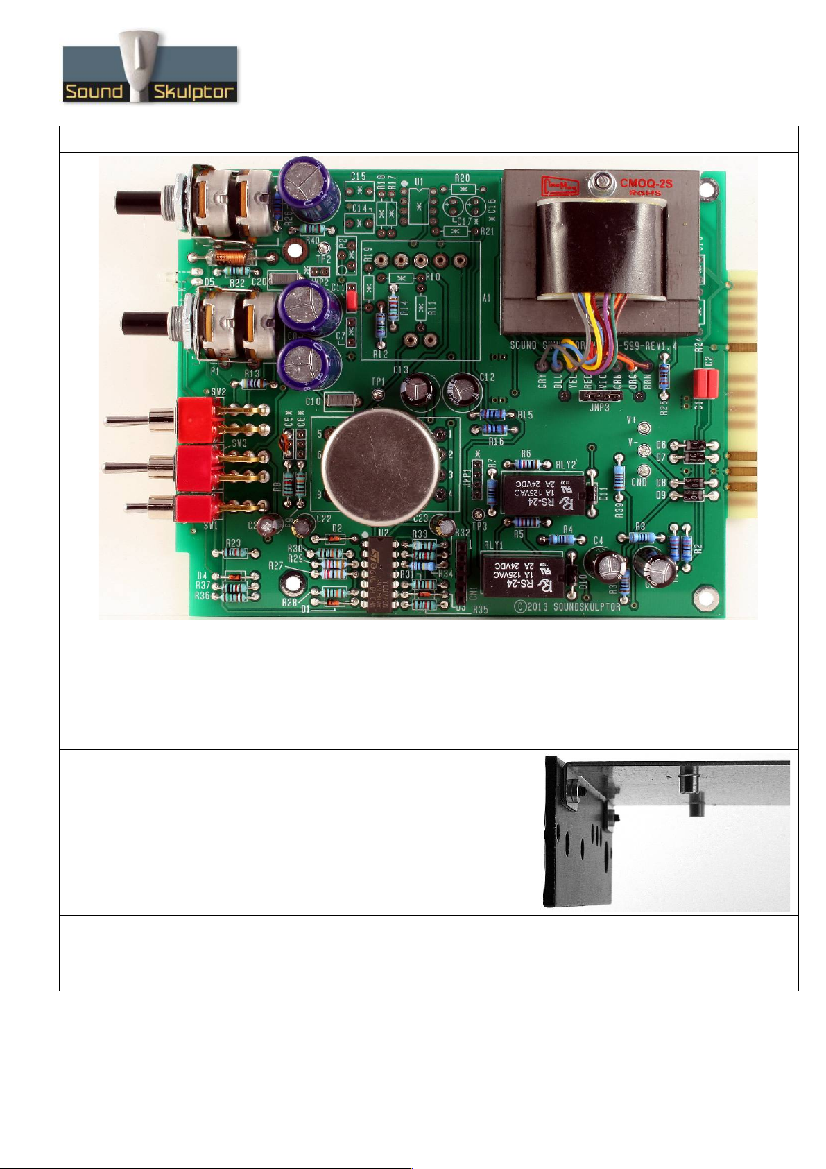
M 5.12 Assembly guide
Safety warning
The kits are main powered and use potentially lethal voltages. Under no circumstance should someone undertake the
realisation of a kit unless he has full knowledge about safely handling main powered devices.
lease read the “DIY guide” before beginning.
rint or open the following documents :
•M 512 Schematics
•M 512 Components layout
•M 512 arts list
•M 512 Test guide
Follow this guide from item number 1 till the end, in this order. The assembly order is based on components height, from
low to high profile, in order to ease the soldering process : The component you are soldering is always taller than the
previously assembled ones and it is pressing nicely against the work area foam.
M 5.12 Assembly guide
1. DOA in Sockets
Solder the 7 pin sockets for the DOA. Solder one at a time. Insert one
socket, turn over the CB and press against a solid but flexible surface like
cork or dense foam then solder. The correct positioning of the sockets is
very important for easy insertion of the DOA.
2. Diodes
Add D1 to D4, D6 to D11. Use a lead forming tool to bend the leads at 0.4”.
Warning : Make sure to respect the direction of the diodes which is marked by a ring on the component
and a double line on the CB marking.
3. Resistors
Add R1 to R40. The resistors marked NC in the parts-list should not be installed.
Control the resistor values with a digital multimeter. Bend the leads at 0.4” with a lead forming tool.
4. Integrated Circuit
Insert U2 and solder. You will need to bend the pins slightly inwards before inserting. Make sure you are
not charged with electrostatic electricity before handling the IC (or remove your shoes).
Warning : Make sure to respect the IC direction, marked by a notch. Do not use a socket because it
would be to high for the Di01 board.
5. Inductor
Add L1. Bend at 0.8”.
Copyright ©2013 SoundSkulptor
www.soundskulptor.com
Document revision 1.1 – Last modification : 15/07/20
M 5.12 Assembly guide
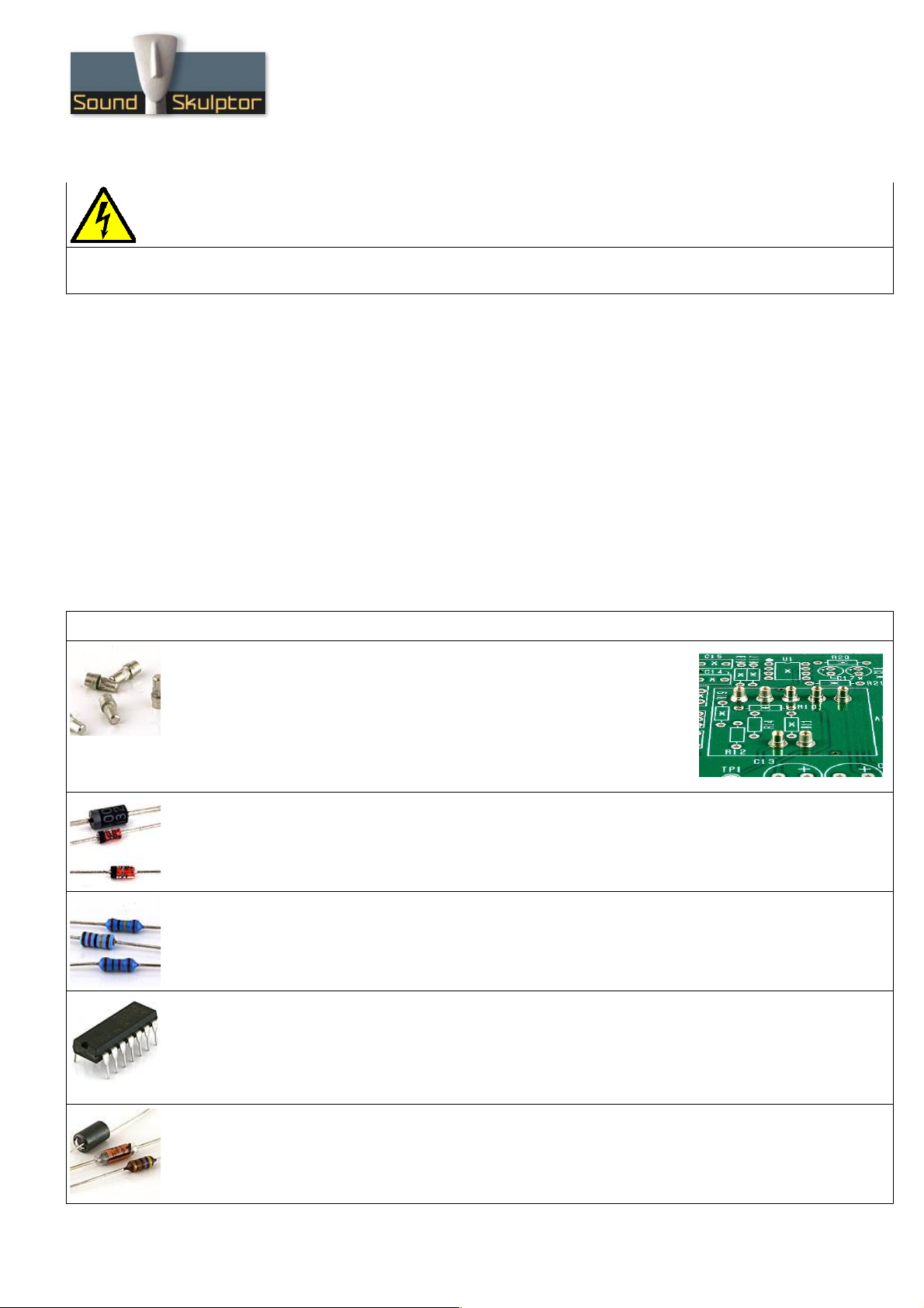
6. Led
Bend the leads of D5 right angle at 6mm from the body taking care of the
anode position (the longest lead).Insert from the CB bottom and solder with
the LED body lined up with the CB
surface.
Warning : it is easy to bend the leads in
the wrong direction !
7. Test pins
Solder the 6 test pins T 1 to T 3, V+, V- and GND.
8. Jumper header
Solder the jumper header JM 3. Solder one pin first, check verticality, then solder the other pins.
9. Connector
Solder the connector socket CN1. Solder one pin first, check verticality, then solder the other pins.
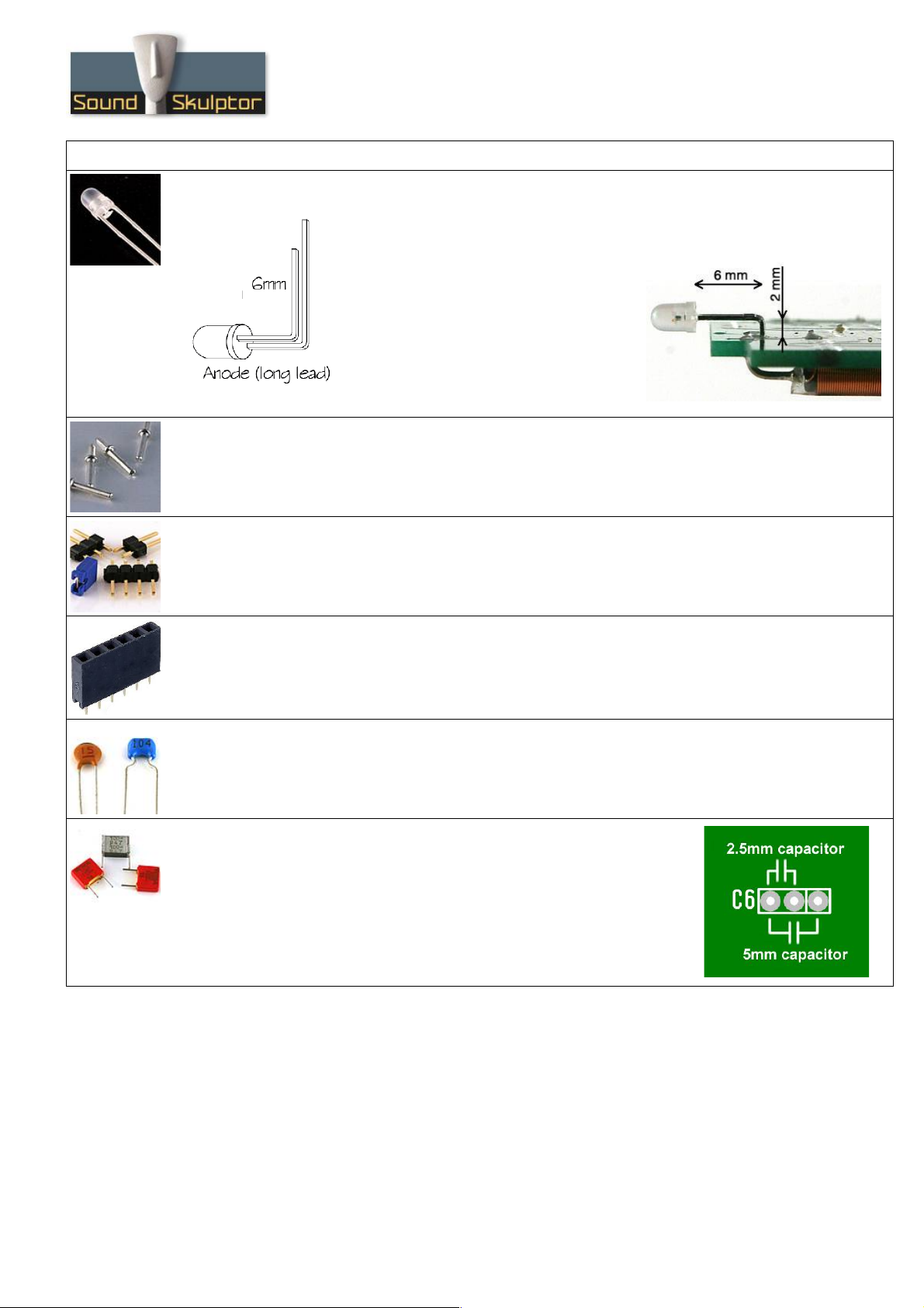
10. Ceramic capacitors
Add C5.
Warning : Some capacitors have provision for 2 sizes. Small size capacitors must be inserted in the
correct holes as shown in the picture.
11. Film capacitors
Add C1, C2, C10, C11, C20.
Warning : Some capacitors have provision for 2 sizes. Small size capacitors
must be inserted in the correct holes as shown in the picture.
Copyright ©2013 SoundSkulptor
www.soundskulptor.com
Document revision 1.1 – Last modification : 15/07/20
M 5.12 Assembly guide
12. Relay
Add RLY1 and RLY2.
13. Small electrolytic capacitors
Add C3, C4, C12, C13, C21, C22, C23.
Solder one lead first, adjust verticality then solder the second lead.
Warning : The +lead must go into the +hole. Do not reverse (they may explode !)
14. Switches
Add SW1, SW2 and SW3. The position of the switches is critical for a good front-plate matching. They
must sit flat on the CB. ress firmly the switch on the CB and solder one of the front pins (housing).
Check verticality and horizontality. Then solder the other pins.
Copyright ©2013 SoundSkulptor
www.soundskulptor.com
Document revision 1.1 – Last modification : 15/07/20
M 5.12 Assembly guide
15. otentiometers 1 & 3
lace the bracket on the potentiometer bush. Do not insert the nut yet. Insert potentiometer and
bracket into the CB holes. Solder the 2 central potentiometer pins, taking care that it sits perfectly flat
on the CB.
Warning : The bracket sometimes prevents a correct positioning of the pot. In that case, angle slightly
the bracket so that it does not come in the way. Il will take its correct position after the pot is soldered.
Once the position is correct, solder the other 4 potentiometer pins.
Now attach the washer and nut to the potentiometer bush and tighten gently.
Last, solder the 4 bracket pins.
16. Input transformer
It is necessary to leave a small gap between the transformer and the CB surface in order to avoid any
electrical contact between the metal case and pads. Fit a piece of double sided adhesive tape under the
transformer, between the pins. It is not necessary to remove the second protective layer from the tape
as it is only used as a spacer.
in 1 on the transformer is identified by a red dot. Insert the transformer, pin 1 into hole number 1.
Start soldering 2 opposite pins, check the position, adjust if necessary then solder the other pins.
Warning : Double check the pin 1 position because this transformer can be mounted backwards!
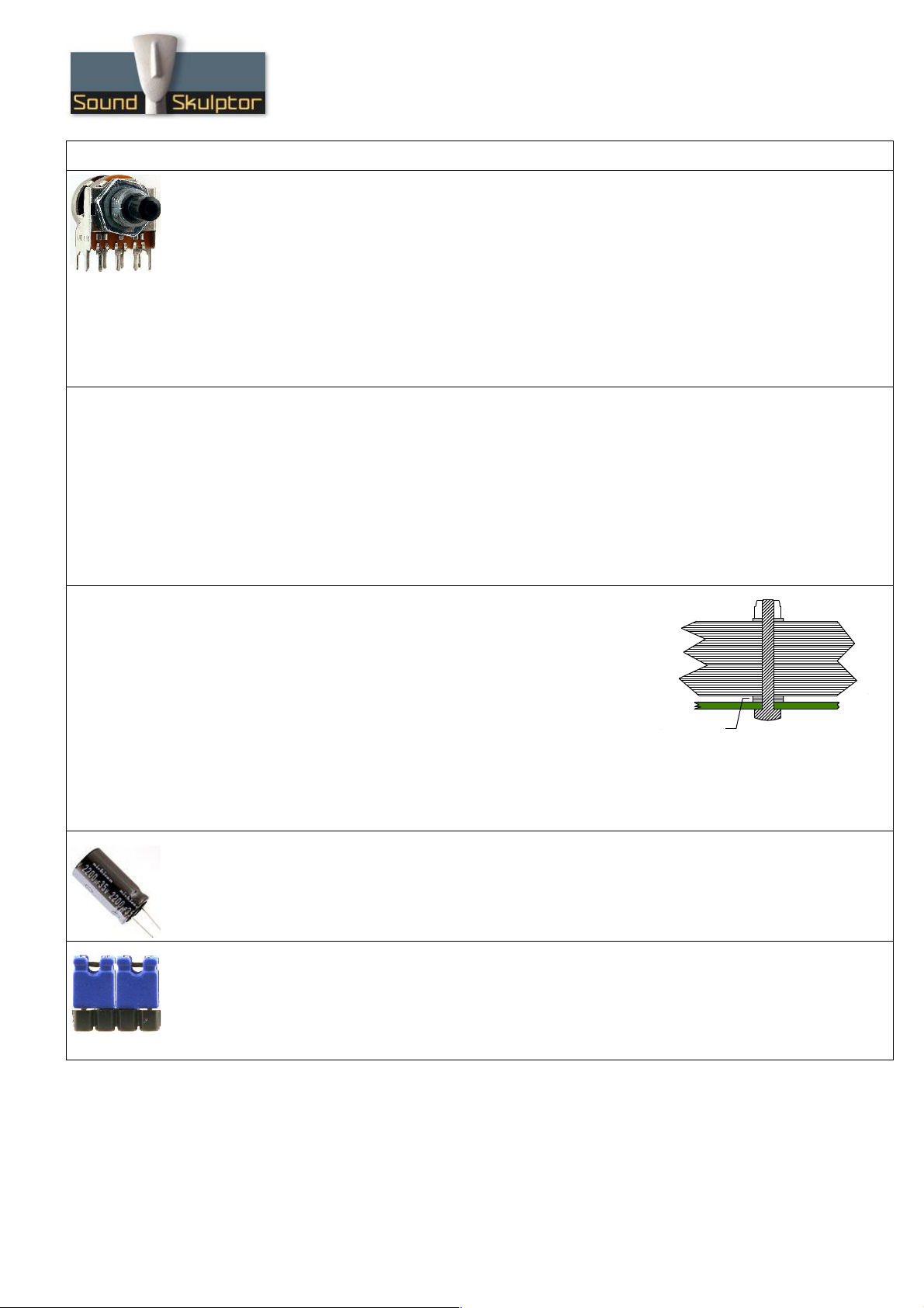
17. Output transformer
The transformer is mounted using two 25mm M3 screws inserted
from the back of the board. Two metal washers are fitted on each
screw to prevent the transformer touching the CB. One more
washer is used before the nut to protect the lams.
Shorten the leads to the necessary length, around 6 cm. Strip on
5mm and tin them. Insert in the pad hole and bend the tinned tip flat
on the pad before soldering. Cut flush.
Warning: There is an error in the CB writings. It is necessary to swap the green and grey wires to keep
the phase correct. The green wire goes into the GRY hole and the grey wire goes into the GRN hole.
18. Large electrolytics
Add C8, C9 and C19.
These capacitors are bipolar so they can be inserted in any direction.
19. Jumpers
Insert 2 jumpers on JM 3.
These jumpers set the output transformer ratio to 1:2. One single jumper placed on the center 2 pins
would set it to 1:1.
Copyright ©2013 SoundSkulptor
Nut
Transformer
CB
1 Washer
2 Washers
www.soundskulptor.com
Document revision 1.1 – Last modification : 15/07/20
M 5.12 Assembly guide
20. Visual check
At this point, brush the solder side with a hard tooth brush to remove any remaining solder bits.
Make a full visual check. Any missing component on the board ? Any remaining component in the box ?
When everything looks correct, proceed with the frame assembly.
21. Frame assembly
Attach the side panel to the front plate with two M3x8 black
countersunk screws.
Warning : Do not confuse the M3x8mm countersunk black
screws with the #4-40 3/8" black screw that are used to
attach the module in the lunchbox.
22. CB mounting
ut the CB in place, switches and pots going through the front panel. Watch out the LED position.
Attach the CB with 4 M3x6mm screws and 4 shake-proof washers.
Copyright ©2013 SoundSkulptor
www.soundskulptor.com
Document revision 1.1 – Last modification : 15/07/20
M 5.12 Assembly guide
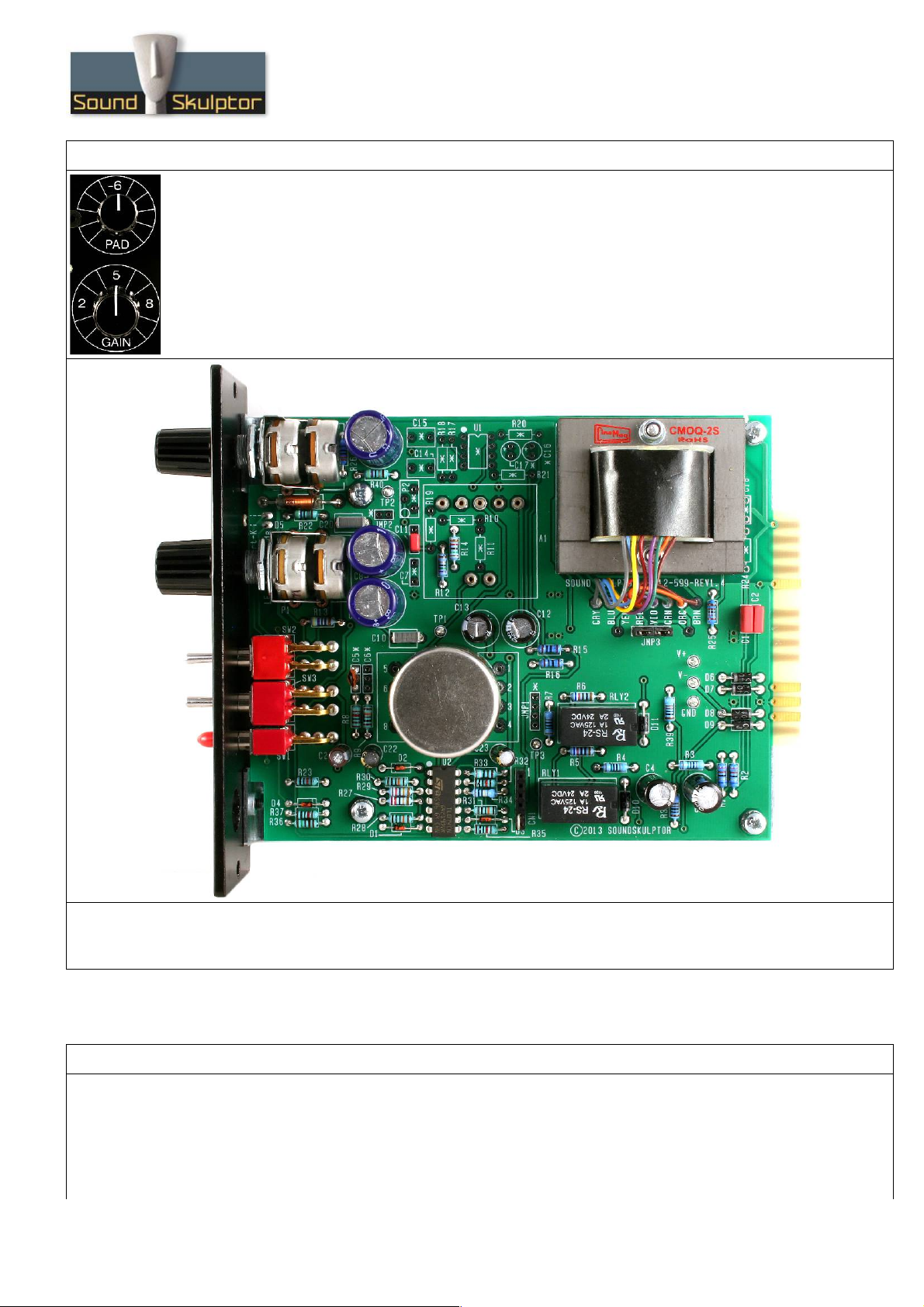
23. Knobs
Attach the 2 knobs.
24. Test
Your M 5.12 is now ready for test. lease follow instructions in the “M 512 Test” document.
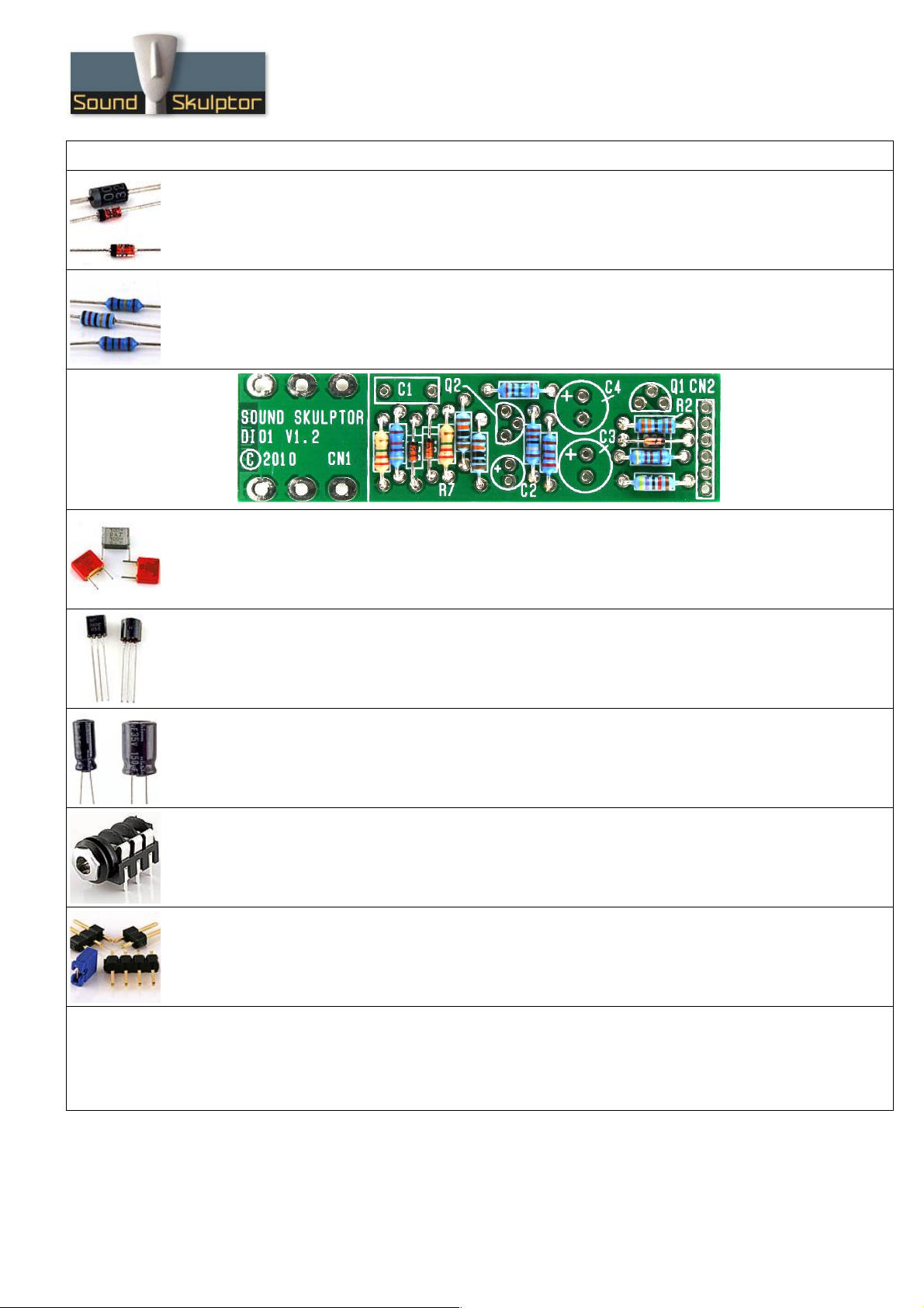
Di01 Assembly guide
rint or open the following documents :
•Di01 Schematics
•Di01 Components layout
•Di01 arts list
Copyright ©2013 SoundSkulptor
www.soundskulptor.com
Document revision 1.1 – Last modification : 15/07/20
Di01 Assembly guide
1. Diodes
Add D1, D2 and D3. Use a lead forming tool to bend the leads at 0.4”.
Warning : Make sure to respect the direction of the diodes which is marked by a ring on the component
and a double line on the CB marking.
2. Resistors
Add R1 to R11.
Control the resistor values with a digital multimeter. Bend the leads at 0.4” with a lead forming tool.
3. Film capacitor
Add C1.
4. Transistors
Add Q1 and Q2.
Warning : Watch out the transistor direction.
5. Electrolytic capacitors
Add C2, C3, C4.
Solder one lead first, adjust verticality then solder the second lead.
Warning : The +lead must go into the +hole. Do not reverse (they may explode !)
6. Jack connector
Add CN1. The position of the socket is important for a good front-plate matching. It must sit flat
on the CB. ress firmly the socket on the CB and solder one of the pins. Check position then solder
the other pins.
7. Connector
Solder the connector CN2. Solder one pin first, check verticality, then solder the other pins.
Warning : the connector pins must be exactly perpendicular to the CB to allow proper insertion in the
preamp board.
8. Visual check
Brush the solder side with a hard tooth brush to remove any remaining solder bits. Make a full visual
check. Any missing component on the board ? Any remaining component in the box ?
The Di01 is ready for testing !
Copyright ©2013 SoundSkulptor
www.soundskulptor.com
Document revision 1.1 – Last modification : 15/07/20
Di01 Assembly guide
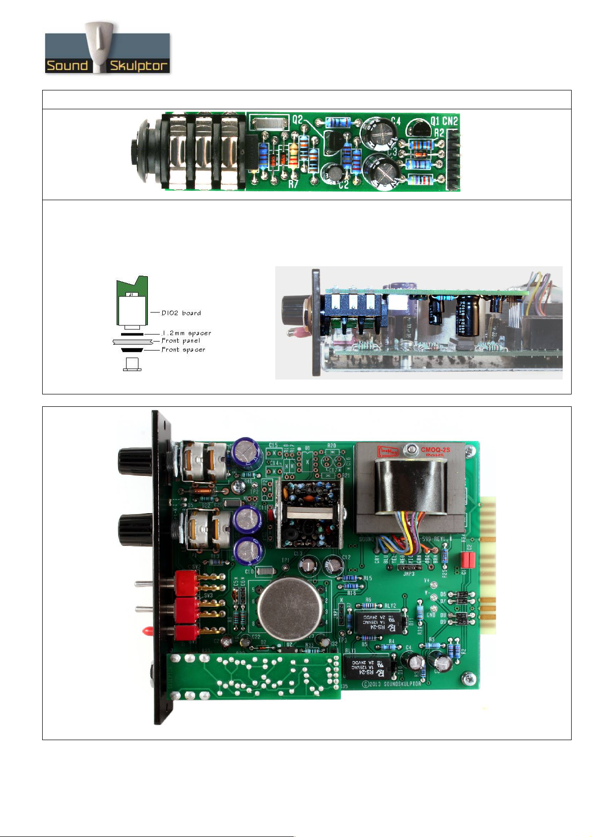
9. Board installation
lace one 1.2mm plastic spacer on the jack sockets and insert into the front panel while fitting the CN2
connector pins into the socket on the preamp CB. Screw in the front nut through the bevelled front
spacer with an M12 socket spanner.
Copyright ©2013 SoundSkulptor
Autres manuels pour MP 512
2
Table des matières
Autres manuels Sound Skulptor Amplificateur

Sound Skulptor
Sound Skulptor MP573 Manuel utilisateur

Sound Skulptor
Sound Skulptor SK25 Manuel utilisateur

Sound Skulptor
Sound Skulptor MP 599 Manuel utilisateur

Sound Skulptor
Sound Skulptor MP 512 Manuel utilisateur

Sound Skulptor
Sound Skulptor MP573 Manuel utilisateur

Sound Skulptor
Sound Skulptor MP73 Manuel utilisateur

Sound Skulptor
Sound Skulptor MP 566 Manuel utilisateur

Sound Skulptor
Sound Skulptor MP66 Manuel utilisateur

Sound Skulptor
Sound Skulptor MP 599 Manuel utilisateur

Sound Skulptor
Sound Skulptor MP573 Manuel utilisateur


