USBPre 2 User Guide and Technical Information
7
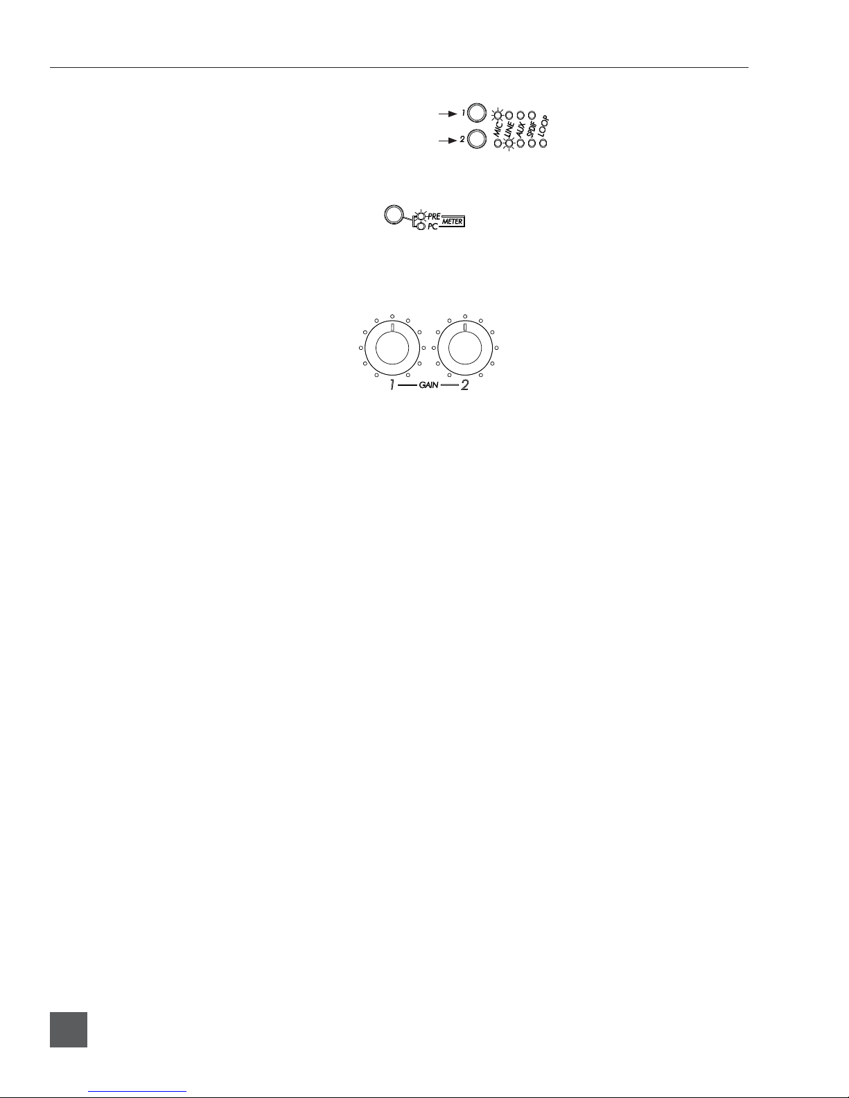
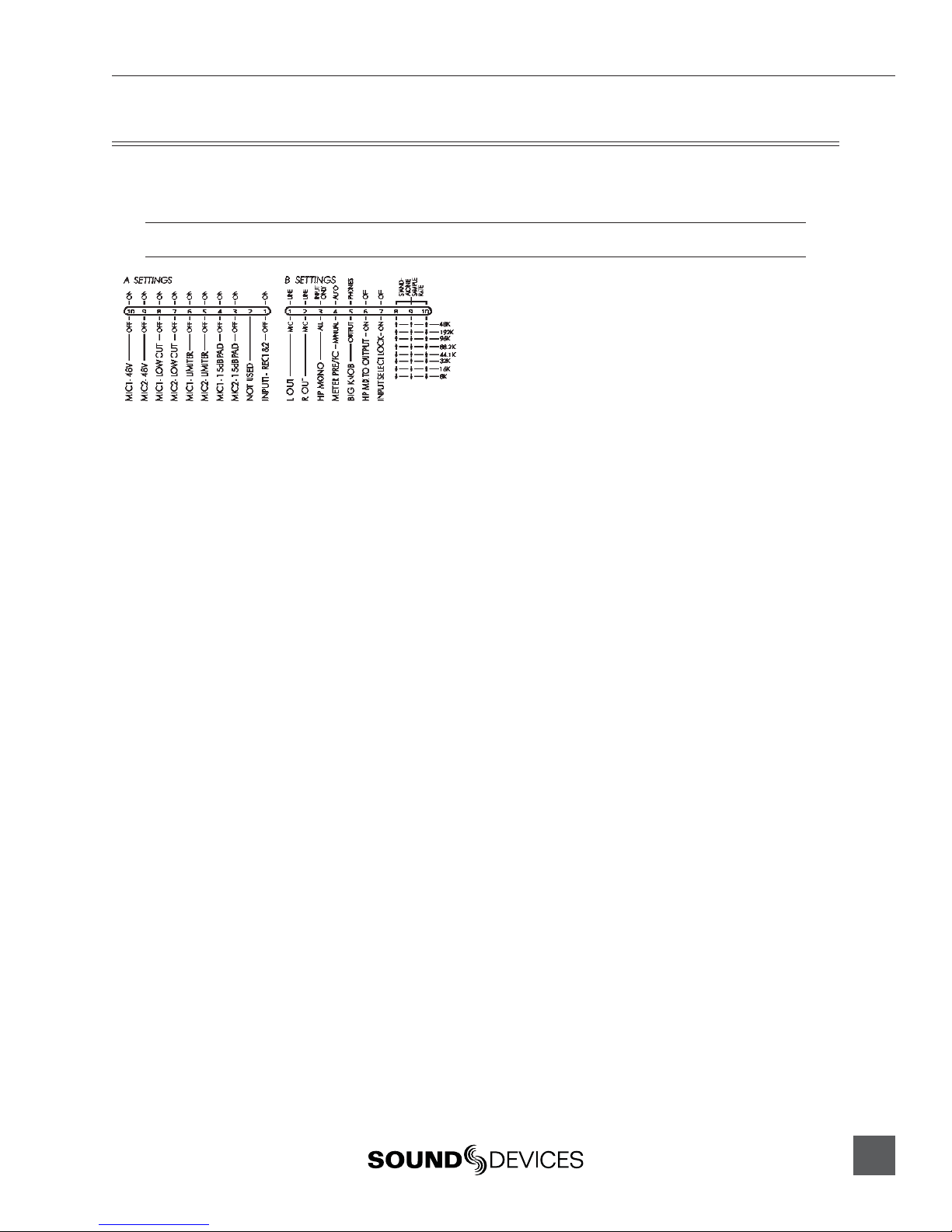
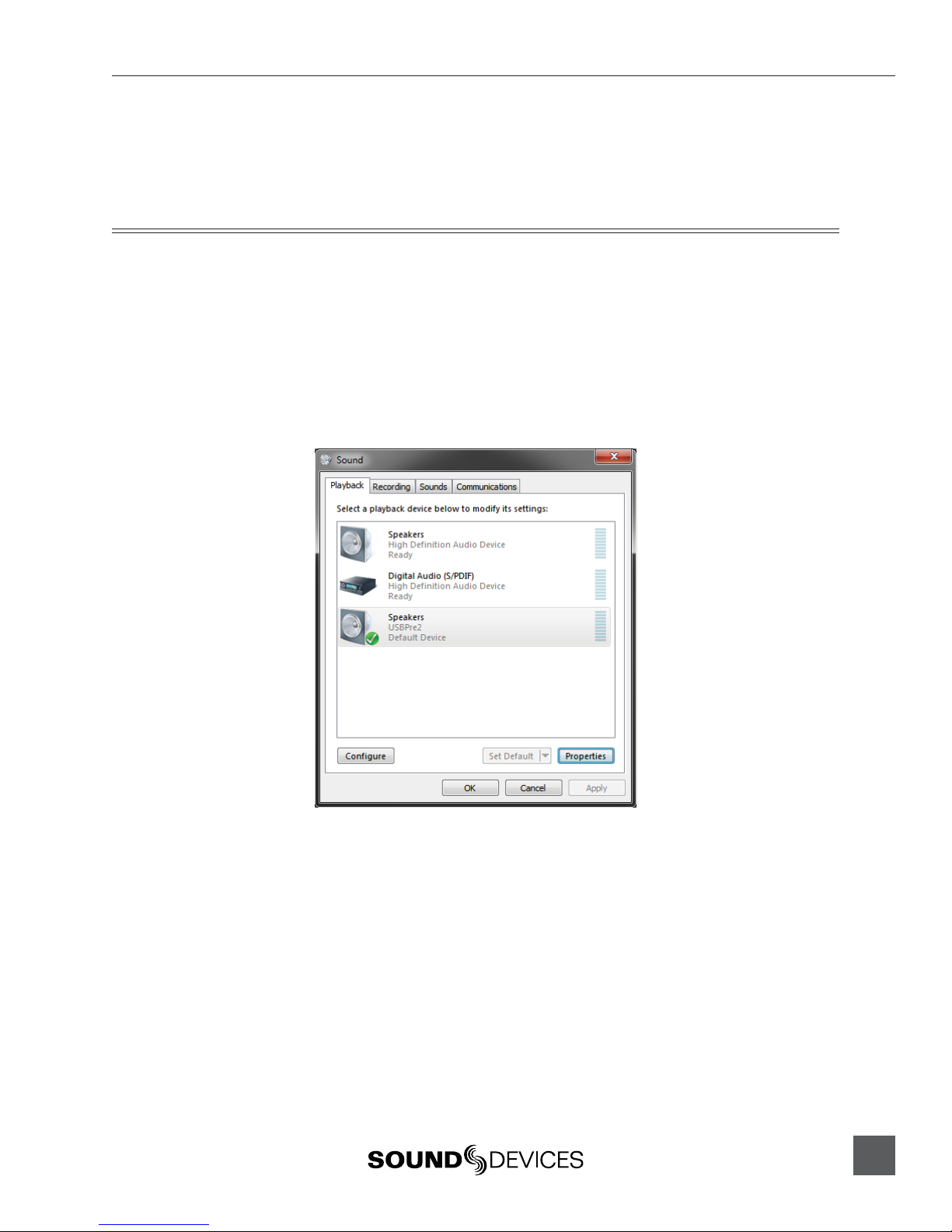
DIP Switch Options
The DIP switches on the back panel of the USBPre 2 can be switched to select various parameters. To
adjust an individual switch, carefully move the switch with a slender tool.
In the following descriptions, “Up” refers to the direction ot the USBPre 2’s top panel.
A Settings
48 Volt Phantom Power (9 and 10)•
Up position engages 48 Volt phantom power
on balanced microphone inputs. Required for
condenser microphones. See Inputs Section.
Low-cut Filter (7 and 8)•
Up position engages low-cut filter on balanced
microphone inputs. -12 dB per octave at 80 Hz.
See Inputs Section.
Limiter (5 and 6)•
Up position engages limiter on balanced micro-
phone inputs. Attenuates signal above -4 dBu.
See Inputs Section.
15 dB Pad (3 and 4)•
Up position reduces gain by 15 dB on balanced
microphone inputs. Useful for sensitive micro-
phones or very loud prgram material. See Inputs
Section.
Input 1 Split•
Up position disables input 2 and routes input 1
signal to both tracks. This routing is pre-gain, so
input gain controls still affect the signal to each
track.
B Settings
Balanced Output Level (1 and 2)•
Determines level of balanced XLR outputs. Up
position: Line level (0 dBu). Down position: Mic
level. (-40 dBu). See Outputs and Monitoring.
HP Mono Function (3)•
Adjusts what signals are summed when HP
MONO is active. Up position: Input signals
only. Down position: Input signals and output
audio from the computer. See Ouputs and Moni-
toring.
Meter PRE/PC (4)•
Adjusts whether or not the meter source
switches automatically when computer audio is
present. Up position: Automatic. Down posi-
tion: Manual. See Ouputs and Monitoring.
HP / Output Knob (5)•
Adjusts which knob controls headphone gain
and which knob controls main output gain. Up
position: Big Knob controls headphone gain and
Small Knob controls main output gain. Down
position: Big Knob controls main output gain
and Small Knob controls headphone gain.
Headphone Signal to Outputs (6)•
Up position: Only computer audio is sent to
outputs. Down position: Main output source is
the same as headphone signal source and affect-
ed by Monitor Mix Control. Note: In Stand-alone
mode, input signal is always routed to the outputs
and this setting has no effect.
Input Select Lock (7)•
Up position: Input Select Buttons function nor-
mally. Down position: Input Select Buttons are
disabled and input source selection is locked.
Stand-Alone Sample Rate (8, 9, and 10)•
Sets the operating sample rate when in Stand-
Alone mode according to the associated
diagram. See Stand-Alone mode. In Soundcard
Mode, sample rate is determined by the com-
puter. See Installation and Connection.