2/8
Form 420 (01.13) ©SOR Inc.
Installation
Use care during installation not to inadvertently move the electrical
detectng element or t’s housng. Movement of ether could dsturb the
relative positions of internal working parts and alter factory-set calibration or
render the device inoperative.
This product should be installed by trained and competent personnel only.
Ensure that all wiring conforms to all applicable local and national electrical codes and
install unit(s) according to relevant national and local safety codes.
Securely mount a pipe kit bracket or base plate as supplied to horizontal member of the
pipe stanchion, channel rack or a flat surface using suitable bolts. The 102 is not position
sensitive, and may be mounted in any position.
Process Connection
The high pressure side (marked Hi) and the low pressure side (marked Lo) have 1/4”
NPT(F) process connections (1/2” NPT(F) optional).
When the process could be considered dirty in terms of suspended particles,
it is recommended that 20-micron in-line lters be installed on the Hi and Lo
pressure ports.
Electrical Connection
Weathertight Models:
Interrupt the electrical power. Remove the top cover plate. The terminal block is standard,
except with B, BB, W or Y high-temperature detecting elements. The insulation is labeled
C - Common, NO - Normally Open, NC - Normally Closed and C2, NO2, NC2 when 2-SPDT
detecting elements are installed.
Explosion Proof Models:
Units in hazardous locations: prior to removal from service, make sure that the
work area is declassied. Failure to do so could result in severe personal injury
or substantial property damage.
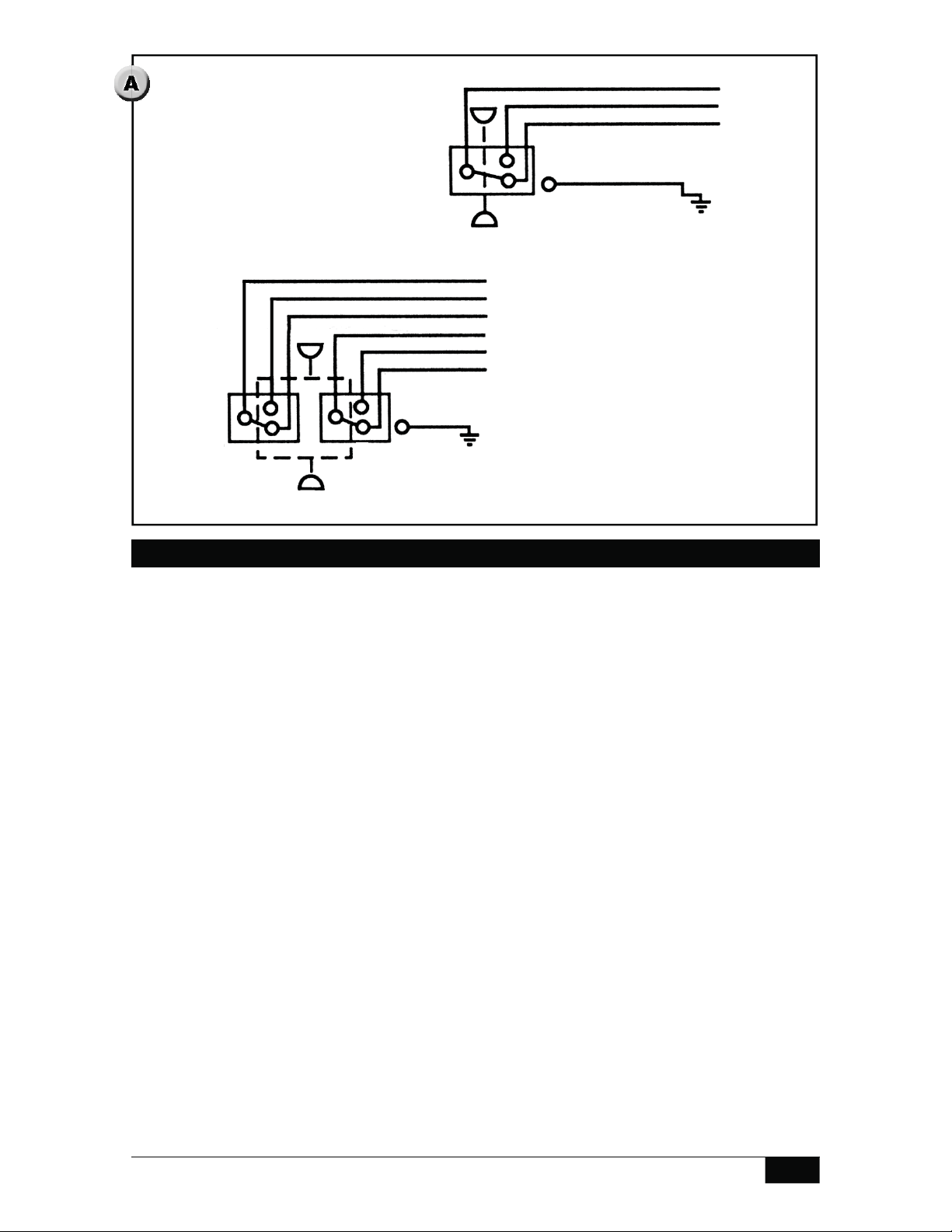
The hermetically sealed detecting element capsule has 18” - 18 AWG wire leads color
coded and marked C - Common, NO - Normally Open, NC - Normally Closed, and G -
Ground (earth) when applicable. When 2-SPDT detecting elements are installed, additional
wires are marked C2, NO2 and NC2. (See schematic.)
Safety Integrity Level (SIL) Installation Requirements
The SOR pressure detectors have been evaluated as Type-A safety related hardware.
To meet the necessary installation requirements for the SIL system, the following
information must be utilized:
Proof Test Interval shall be one year.
Units may only be installed for use in Low Demand Mode.
Products have a HFT (Hardware Fault Tolerance) of 0, and were evaluated in a
1oo1 (one out of one) configuration. Form 1538 (03.12) ©2012 SOR Inc.