
Solid State Logic XLogic Super-Analogue Manuel utilisateur

Solid State Logic
Super-Analogue™ Outboard
Owner’s Manual
82S6XL070A
S U P E R A N A L O G U E
C H A N N E L A D C

As research and development is a continual process, Solid State Logic reserves the right
to change the features and specifications described herein without notice or obligation
E&OE
Revision 0A, May 2004
Minor changes, November 2004
Minor changes, June 2005
Solid State Logic
Begbroke, Oxford, England, OX5 1RU • +44 (0)1865 842300
320 West 46th Street, 2nd Floor, New York, NY 10036, USA • +1 (1) 212 315 1111
Suite 401, 5757 Wilshire Blvd, Los Angeles, CA 90036, USA • +1 (1) 323 549 9090
3-55-14 Sendagaya, Shibuya-Ku, Tokyo 151-0051, Japan • +81 (0)3 5474 1144
7 bis, rue de la Victoire, le Blanc Mesnil, Paris 93150, France • +33 (0)1 48 67 84 85
Via Timavo 34, 20124 Milano, Italy • +39 (0)39 2328 094
Visit SSL at URL: http://www.solid-state-logic.com
© Solid State Logic
All Rights reserved under International and Pan-American Copyright Conventions
Solid State Logic, SSL and XLogic are trademarks of Solid State Logic
All other product names and trademarks are the property of their respective owners
No part of this publication may be reproduced in any form or
by any means, whether mechanical or electronic, without the
written permission of Solid State Logic, Oxford, England

Contents
1. Introduction 3
Warranty
2. Safety Considerations 4
Definitions
Electrical Safety Warnings
Installation
3. Installation 6
Supplied Parts
Tools Required
Procedure
4. Operation 11
Synchronisation
Sample Rates
Appendices 15
A. Internal Links
B. Connector Details
C. Electronic Specification
D. Physical Specification
E. Environmental Specification
Contents
Page 1
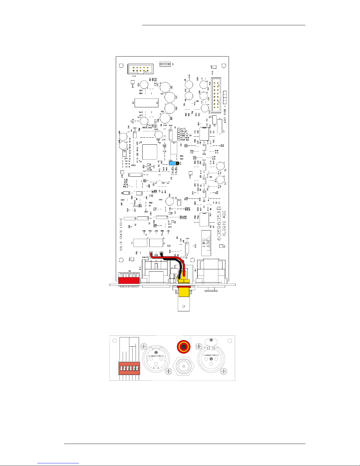
Plan (top) and elevation (lower) of the 629605 Channel ADC card
XLogic Channel ADC Owner’s Manual
Page 2
AES OUT SPDIF OUT
SYNC IN RIGHT IN
SAMPLE
RATE
SYNC
Fs x
44.1
1/4
1/2
AES
Fs
INT
Fs = 48
4 SINGLE / 2
4 SINGLE / 4
WD CLK
256 x Fs
EXT
ON
123456

1. Introduction
The XLogic Channel ADC card is a small PCB assembly containing a high quality 24-bit stereo ADC.
The card is intended to be fitted inside the XLogic Channel unit to provide immediate A to D
conversion at any of the common sample rates between 44.1kHz and 192kHz. The ADC can be
synchronised either to internal crystal or an external word clock or AES/SPDIF sync source. Digital
output from the card is provided in both balanced AES and un-balanced SPDIF formats.
Because the XLogic Channel unit is a mono unit, a second balanced line-level input to the ADC card is
provided. This allows connection of, for example, a second XLogic Channel unit to enable full use of
the AES/SPDIF stereo data stream.
The object of this manual is to provide purchasers of the XLogic Channel ADC card with information
in the following areas:
• Safety considerations
• Installation instructions
• Operational instructions
• Connector pin-outs
• Specifications and physical dimensions
Please Note
The XLogic Channel ADC card is a hardware upgrade for the XLogic Channel unit – it must be
installed before it can be used. Full instructions to achieve this are provided within this
document, however, if you are unsure about performing this please contact your local Solid State
Logic distributor who will be happy to arrange to install it for you. Do note that a charge may be
levied for this service.
Warranty
The warranty period for this card is 12 months from date of purchase.
In Warranty Repairs
In the event of a fault during the warranty period the unit must be returned to your local distributor
who will arrange for it to be shipped to Solid State Logic for repair. All units should be shipped to Solid
State Logic in their original packaging. Solid State Logic can not be held responsible for any damage
caused by shipping units in other packaging. In such cases Solid State Logic will return the unit in a
suitable box, which you will be charged for. Please do not send manuals, power leads or any other
cables - Solid State Logic can not guarantee to return them to you. Please also note that warranty
returns will only be accepted as such if accompanied by a copy of the receipt or other proof of purchase.
Out of Warranty Repairs
In the event of a fault after the warranty period has expired, return the unit in its original packaging to
your local Solid State Logic distributor for shipment to Solid State Logic. You will be charged for the
time spent on the repair (at Solid State Logic's current repair rate) plus the cost of parts and shipping.
Introduction
Page 3

2. Safety considerations
This section contains definitions and warnings, and practical information to ensure a safe working
environment. Please take time to read this section before undertaking any installation work.
Definitions
‘Maintenance’
All maintenance must be carried out by fully trained personnel. Note: it is advisable to observe suitable
ESD precautions when maintenance to any part is undertaken.
‘Non-User Adjustments’
Adjustments or alterations to the equipment may affect the performance such that safety and/or
international compliance standards may no longer be met. Any such adjustments must therefore
only be carried out by fully trained personnel.
‘Users’
This equipment is designed for use solely by engineers and competent operators skilled in the use
of professional audio equipment.
‘Environment’
This product is a Class A product intended to form an integrated component part of a professional
audio recording, mixing, dubbing, film, TV, radio broadcast or similar studio wherein it will
perform to specification providing that it is installed according to professional practice.
Electrical Safety Warning
When installing or servicing any item of Solid State Logic equipment with power applied, when
cover panels are removed, HAZARDOUS CONDITIONS CAN EXIST.
These hazards include: High voltages
High energy stored in capacitors
High currents available from DC power busses
Hot component surfaces
Any metal jewellery (watches, bracelets, neck-chains and rings) that could inadvertently come
into contact with uninsulated parts should always be removed before reaching inside powered
equipment.
XLogic Channel ADC Owner’s Manual
Page 4

Installation
Voltage Selection and Fusing
The XLogic Channel ADC card is fitted internally to the XLogic Channel unit and so does not require
a mains supply.
CE Certification
Modifying any of the metalwork of the XLogic Channel unit to which this assembly is fitted in any way
may adversely affect the CE certification status of the product.
FCC Certification
The XLogic Channel unit, with an ADC card fitted, has been tested and found to comply with the limits
for a Class A digital device, pursuant to part 15 of the FCC Rules. These limits are designed to provide
reasonable protection against harmful interference when the equipment is operated in a commercial
environment. This equipment generates, uses, and can radiate radio frequency energy and, if not
installed and used in accordance with the instruction manual, may cause harmful interference to radio
communications. Operation of this equipment in a residential area is likely to cause harmful
interference in which case the user will be required to correct the interference at his own expense.
The above certifications are valid provided the ADC card is fitted to an XLogic Channel assembly, as instructed
within this document.
Safety Considerations
Page 5
XLogic Channel ADC Owner’s Manual
Page 6
3. Installation
This section details how to install the XLogic Channel ADC card in an XLogic Channel unit. Before you
begin, please consider these points:
• Carefully read through these instructions first.
• Check that all of the component parts of the kit are present.
• Check that you have the required tools to hand before attempting installation.
• Consider if you need to adjust the operating level of the card. There are two options, set by an
internal jumper:
+24dBu (position ‘1-2’) 0dBu ≈ –24dB FS (SMPTE standard and factory default)
+18dBu (position ‘2-3’) 0dBu ≈ –18dB FS (EBU standard)
Supplied Parts
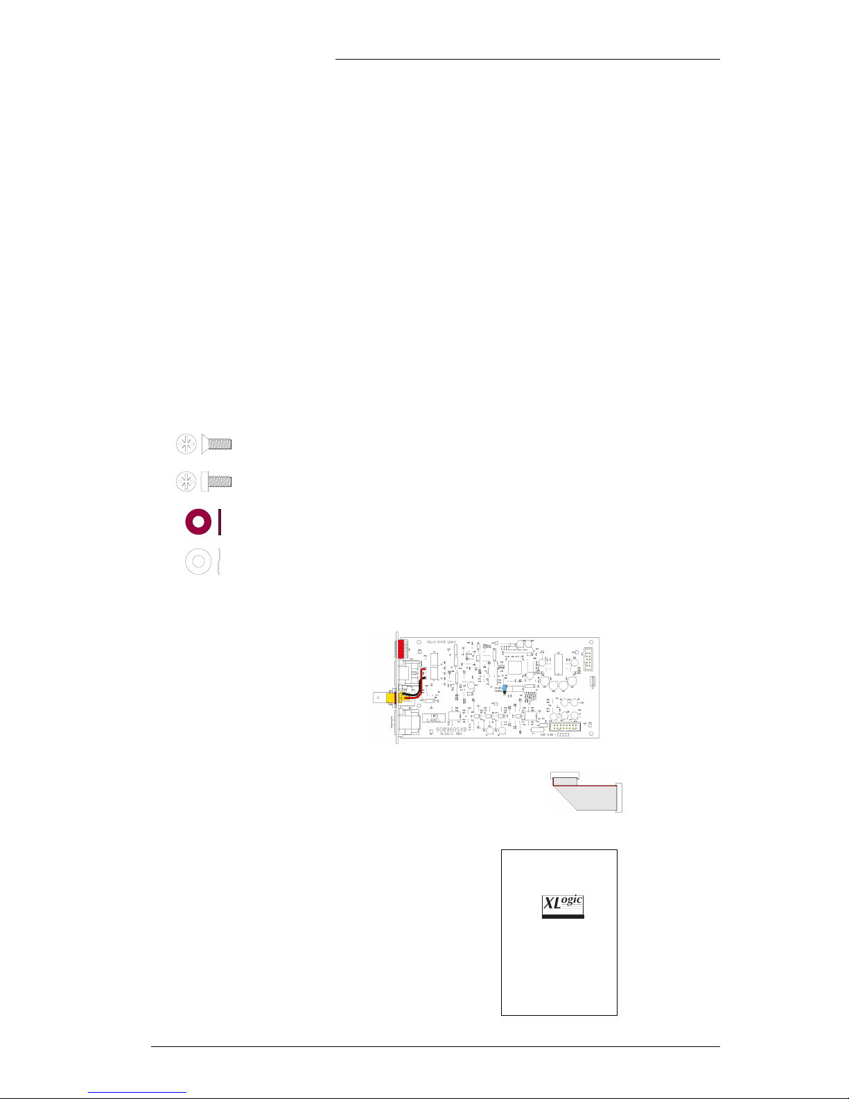
The following hardware is supplied with the XLogic Channel ADC Card kit:
Qty Item Part Number & Description Notes
10 51DD20CB - Screw M3 x 6mm Csk Pozi Zp Spares, for the top cover…
6 51DD25CB - Screw M3 x 6mm Pan Pozi Zp ADC Card fixings
4 51DDNH5Z - Washer M3 Fibre Internal ADC Card fixings
2 51DDNQ5B - Washer M3 Crinkle Shakeproof Zp External ADC Card fixings
Also included in this kit are one of each of the following:
• 629605X1 - S/A XLogic ADC
This card should be left in its sealed,
anti-static bag, until you are ready to
install it.
Along with the card there should also be a short ribbon cable
(either loose or plugged into PL5 on the ADC card).
• 82S6XL070A - XLogic Channel ADC Installation Guide
(this document)
Solid State Logic
Super-Analogue™ Outboard
Owner’s Manual
82S6XL070A
S U P E R A N A L O G U E
C H A N N E L A D C

Tools Required
Other than any tools which may be required to remove the XLogic Channel unit from any racking or
studio furniture, the following tool is all that is required to install this card:
Qty Part No. Description Notes
1 80C2CECC 1-point pozi-drive screwdriver This is not a ‘philips’ screwdriver!
Do however, please note the following:
• The geometry of ‘philips’ and ‘pozi-drive’ screws and screwdrivers are
subtly different and so the two types of screw and screwdriver are not
inter-changable. It is however normally quite simple to differentiate
between the two types of screwdriver as the tip of a ‘pozi-drive’
screwdriver is quite blunt and has additional ‘flutes’ between each of the
four blades that make up the head, as shown in the illustration to the
right – a ‘philips’ screwdriver will be missing the flutes and has a much
sharper tip.
• Most ‘pozi-drive’ screws have an echo of the additional ‘flutes’ marked
on the head of the screw - take a look at the illustrations opposite and the
screws that we have supplied.
• The tip of any screwdriver should firmly locate in the screwhead – if it
does not then it is either the wrong type, the wrong size or worn out.
• If you neither possess nor can obtain a 1-point pozi-drive screwdriver
locally, it should be possible to obtain one from your local Solid State
Logic distributor.
Installation
Page 7
Additional
‘flutes’
Blunt tip

Procedure
Remove the XLogic Channel unit from any racking or studio furniture, and place it on a suitable clean,
flat work surface. Ensure that the work area is adequately illuminated and then proceed as follows:
1. Using a 1-point pozi-drive screwdriver, remove the 15 M3 x 6mm csk screws which secure the top
cover to the unit. Lift the cover off and place it safely to one side.
2. Turn the unit around and using the same screwdriver, remove the two M3 x 6mm panhead screws
which fix the ADC blanking plate to the rear of the unit. The blank plate, screws and washers
removed can be discarded although it is recommended that they be retained in case it is found
necessary to remove the ADC card at a later date.
XLogic Channel ADC Owner’s Manual
Page 8
Remove:
15 x
Remove ADC Blanking Plate
Remove:
2 x , plus 2 x
Ce manuel convient aux modèles suivants
1
Table des matières
Autres manuels Solid State Logic Matériel de musique

Solid State Logic
Solid State Logic 82S6XL090A Manuel utilisateur
Solid State Logic
Solid State Logic XLogic Super Analogue Manuel utilisateur
Solid State Logic
Solid State Logic XL-Desk Manuel utilisateur
Solid State Logic
Solid State Logic SSL12 Manuel utilisateur
Solid State Logic
Solid State Logic XLogic SDI-MADI Manuel utilisateur

Solid State Logic
Solid State Logic XLogic Super-Analogue X-Rack Manuel utilisateur
Solid State Logic
Solid State Logic XLogic SDI-MADI Manuel utilisateur


