SOLID AIR FDC25 Manuel utilisateur

1| Circular re damper user manual 05/2020
SOLID AIR
®
CLIMATE SOLUTIONS • T +31 598 36 12 21 • www.solid-air.nl •mail@solid-air.nl
TECHNICAL MANUAL
Rectangular Fire Damper
FDC25 |FDC40
TABLE OF CONTENTS
1. PRODUCT PRESENTATION ..................................................................................................2
2. DIMENSIONAL RANGE.......................................................................................................... 3
3. DIMENSIONS ............................................................................................................................4
4. STORAGE AND HANDLING .................................................................................................6
5. INSTALLATION AND IMPLEMENTATION........................................................................6
6. CONTROL MECHANISM..................................................................................................... 21
7. ELECTRICAL CONNECTIONS.............................................................................................23
8. OTHER MECHANISMS ........................................................................................................24
9. EVOLUTION OF SERVICE KITS......................................................................................... 26
10. MAINTENANCE..................................................................................................................... 26

2| Circular re damper user manual 05/2020
SOLID AIR
®
CLIMATE SOLUTIONS • T +31 598 36 12 21 • www.solid-air.nl •mail@solid-air.nl
1. P
Fire dampers FDC25/FDC40 are installed in ventilation ducts between re compartments in order
to stop the spread of re and smoke trough the duct. They have a modular (manual or magnet)
or motorized mechanism, entirely outside the wall. Casing is made out of galvanized steel sheet,
damper blade is made of special insulating material, and damper blade shaft and push rod are made
of stainless steel. Bearings are made of brass, seals of polyurethane and elastomer. The re damper
can be equipped with a simple mechanism with thermal fuse, or with solenoid actuator mechanism
or with electric actuator mechanism..
• Tested according to EN 1366-2 up to 500 Pa
• Airtightness according to standard EN 1751 class C
• Approved for installation in a concrete wall, a concrete slab, plasterboard wall and gpsum
blocks wall
• Operating mechanism completely outside the wall
• Easy to install
• Maintenance free
1. Galvanized steel casing
2. Fire resistant damper blade
3. Control mechanism
4. Intumescent joint
5. Connection anges
6. Product marking on the casing
7. Thermal fuse
1. Gypsum layers
2. Intumescent joint
3. Cold smoke seal
4. Boundary layer
1
3
4
5
2
6
7
1
2
3
4

3| Circular re damper user manual 05/2020
SOLID AIR
®
CLIMATE SOLUTIONS • T +31 598 36 12 21 • www.solid-air.nl •mail@solid-air.nl
2. D
In decimeters:
Free area for dimensions Ø100 - 315 (blade 25 mm) (dm²) = [(π x (Ø-3)2/4)-25 x (Ø-5)]/10 000
Free area for dimensions Ø350 - 800 (blade 40 mm) (dm²) = [(π x (Ø-3)2/4)-40 x (Ø-5)]/10 000
In meters:
Free area for dimensions Ø100 - 315 (blade 25 mm) (m²) = [(π x (Ø-3)2/4)-25 x (Ø-5)]/1 000 000
Free area for dimensions Ø350 - 800 (blade 40 mm) (m²) = [(π x (Ø-3)2/4)-40 x (Ø-5)]/1 000 000
Diameter (mm) Gross section (dm²) Netto area (dm²)
FDC25
100 0.74 0.50
125 1.17 0.87
160 1.93 1.55
200 3.05 2.56
250 4.79 4.18
300 6.18 5.74
315 7.64 6.87
FDC40
355 9.73 8.33
400 12.37 10.79
450 15.69 13.91
500 19.39 17.41
630 30.86 28.36
710 39.24 36.42
800 49.86 46.68
Diameter (mm) Gross section (dm²) Netto area (dm²)
FDC
Applique
100 3.30 0.50
125 3.80 0.87
160 5.11 1.55
200 6.16 2.56
250 8.55 4.18
315 12.25 6.87

4| Circular re damper user manual 05/2020
SOLID AIR
®
CLIMATE SOLUTIONS • T +31 598 36 12 21 • www.solid-air.nl •mail@solid-air.nl
3. D
380 ∅D/2+12 ∅D/2+22
220
Y
D
AC
D
∅D
E
380 ∅D/2+12 ∅D/2+22
∅D
Y
101
E
A
E
Y
D
AC ∅D
380 ∅D/2+12
C
∅D/2+22
FDC25-R
FDC40-R
FDC25/40 M
Product A C D E
Belimo BFL (M) 25 200 90 120
BFN (M) 25 225 100 120
Klimaoprema
-R (FDC 25) 55 150 105 150
-R (FDC 40) 55 200 105 200
-EMP (FDC 25/40) 55 200 105 200

5| Circular re damper user manual 05/2020
SOLID AIR
®
CLIMATE SOLUTIONS • T +31 598 36 12 21 • www.solid-air.nl •mail@solid-air.nl
∅D
380 100 45
∅D+A
(∅D/2)+80 (∅D/2)+94
(∅D/2)+80 (∅D/2)+124
380 100 45
∅D
∅D+A
45
∅D+A
380
145
∅D+160
45
∅D+A
380
145
∅D+160
(∅D/2)+80 (∅D/2)+124
380 100 45
∅D
∅D+A
∅D
380 100 45
∅D+A
(∅D/2)+80 (∅D/2)+94
FDC APPLIQUE
Damper diameter ØD [mm] Applique frame diameter [mm]
100 Øn + 105 mm
125 - 180 Øn + 95 mm
200 - 315 Øn + 80 mm
Y = (Øn/2) - 110 (mm)
X* = (Øn/2) - 270 (mm)
*(dimension X is same as Y
(blade lenght outside of housing)
but opposite side

6| Circular re damper user manual 05/2020
SOLID AIR
®
CLIMATE SOLUTIONS • T +31 598 36 12 21 • www.solid-air.nl •mail@solid-air.nl
4. S
As a safety element, the re damper must be stored, handled and installed carefully.
Pay attention to:
• unload in a dry area
• avoid any shocks
• do not use the damper as a workbench or scaolding
• do not t the small dampers in the large one
The damper must be stored in a dry place, and kept out of water and frost. It should not be
stacked beyond the original packaging. It must be properly stowed so as to prevent any damage or
deformation resulting from an impact or high humidity. It must not be exposed to direct sunlight to
prevent premature aging of the thermal fuse. Once the damper is installed, the mechanism should
be kept away from any projections (cement, paint, ocking, water, dust) that may harm its operation.
The damper must be protected against the risk of heavy condensation. The intumescent joints are
essential for the re resistance of the damper, all mechanical actions on the refractory parts are to
be excluded. All precautions shall be taken to ensure that premature aging of the damper does not
occur before it is actually installed. The actions of wedging and caulking during the sealing of the
dampers must not cause deformations that will alter the good functioning of the damper and in
particular the closing of the blade.
5.
5.1
• Mounting is possible with the blade axis in horizontal or in vertical position
• The installation must comply with the tests that were performed during certication,
as explained in 8.2
• Avoid any obstruction of the moving blade by the connected ducts
• The class of air-tightness is maintained in case the installation of the damper is made in
accordance with the technical manual
• Operating temperature: 50 °C max
• For indoor use only
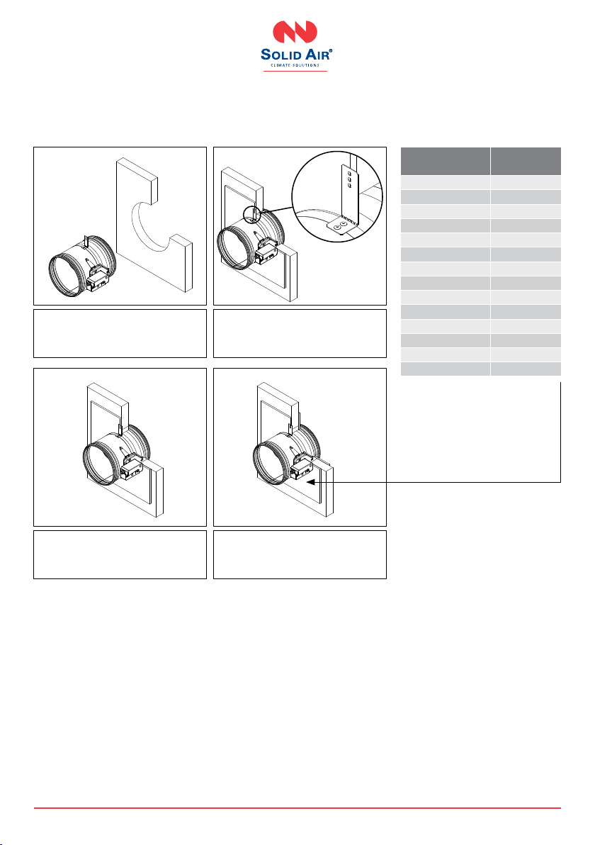
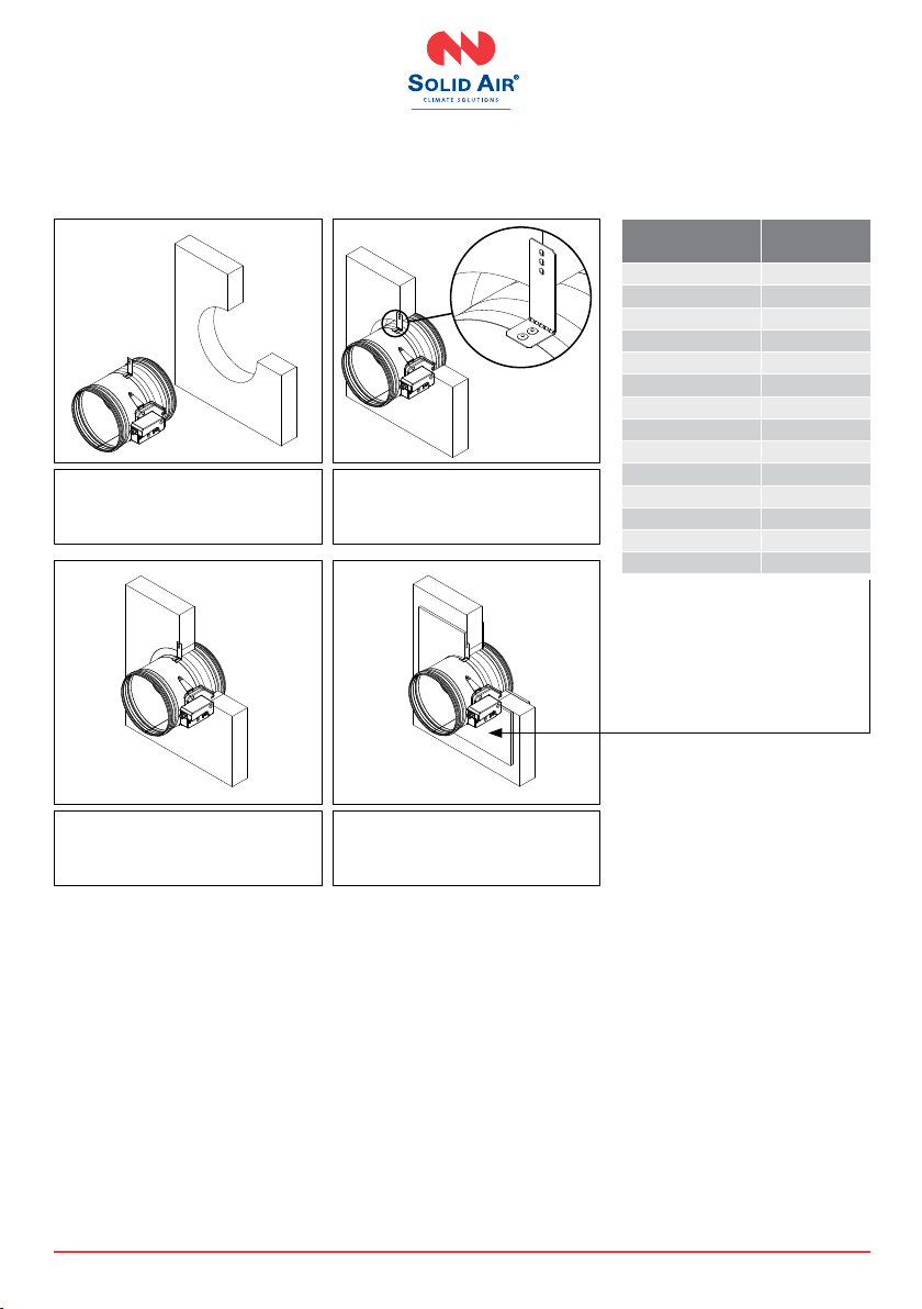
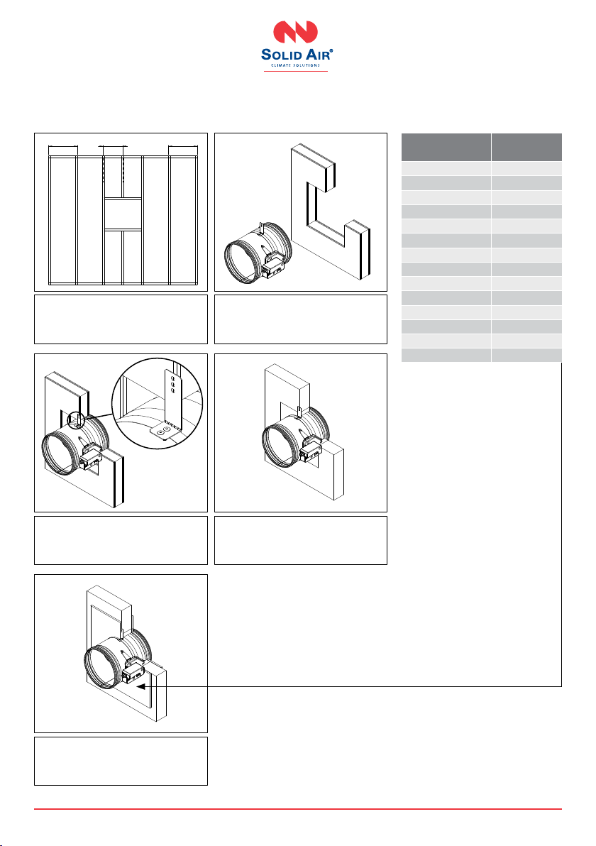
The FDC25/FDC40 re damper is always tested in standardized support frames (both in a concrete
wall and in a exible wall) in accordance with EN 1366-2: 1999 table 3/4/5. The results obtained are
valid for all similar support frames which have a thickness and/or density and/or re resistance
similar or greater than the one of the test.
Minimum opening hole for re damper instalation:
Damper size - ØD [mm] Opening size - A (minimum)
ØD < 160 ØD + 85
180 < ØD < 315 ØD + 75
315 < ØD < 450 ØD + 65
ØD > 450 ØD + 55

7| Circular re damper user manual 05/2020
SOLID AIR
®
CLIMATE SOLUTIONS • T +31 598 36 12 21 • www.solid-air.nl •mail@solid-air.nl
5.2 I
5.2.1 Concrete wall and reinforced concrete wall installation
The wall is composed of concrete blocks (minimum density of 550 kg/m³) and with a minimum thickness
of 100 mm.
5.2.2 Aerated concrete ceiling installation and reinforced concrete ceiling installation
The ceiling is made of aerated concrete with a minimum density of 550 kg/m³ and a minimum thickness
of 100 mm.
Place the damper in an opening
according to table (on page 6)
Fix the damper to the wall using screws
(screw hole is 6 mm in diameter)
Fill the space between the damper
and the wall with mortar
Place the damper in an opening
according to table
(on page 6)
Fix the damper to the slab using
screws (screw hole is 6 mm in
diameter)
Fill the space between the damper
and the slab with mortar

8| Circular re damper user manual 05/2020
SOLID AIR
®
CLIMATE SOLUTIONS • T +31 598 36 12 21 • www.solid-air.nl •mail@solid-air.nl
5.2.3 Gypsum blocks wall 70 mm
The wall is composed of gpsum blocks (minimum density of 995 kg/m³), and with minimum thickness
of 70 mm.
Place the damper in an opening
according to table (on page 6)
Fix damper and GKF gpsum boards
(12.5 mm thick) to wall with screws
(screw hole is 6 mm in diameter)
Fill the space between the damper
and the wall with mortar
Cover the mortar with GKF gpsum
boards (12.5 mm thick)
*The Kit is universal for
all dimensions and must
be cut to t the specic
dimensions of the damper
Diameter of the
damper (mm)
Mounting
kit
100 60061429
125 60061430
160 60061431
200 60061432
250 60061433
315 60061435
355 60061436
400 60061437
450 60061438
500 60061439
560 60061440
630 60061441
710 60061442
800 60061443

9| Circular re damper user manual 05/2020
SOLID AIR
®
CLIMATE SOLUTIONS • T +31 598 36 12 21 • www.solid-air.nl •mail@solid-air.nl
5.2.4 Gypsum blocks wall 100 mm
The wall is composed of gpsum blocks (minimum density of 995 kg/m³), and with minimum thickness
of 100 mm.
Fix the damper to the wall using screws
(screw hole is 6 mm in diameter)
Fill the space between the damper and
the wall with mortar
Cover the mortar with GKF gpsum
boards (12.5 mm thick)
Place the damper in an opening
according to table (on page 6)
*The Kit is universal for
all dimensions and must
be cut to t the specic
dimensions of the damper
Diameter of the
damper (mm)
Mounting
kit
100 60061429
125 60061430
160 60061431
200 60061432
250 60061433
315 60061435
355 60061436
400 60061437
450 60061438
500 60061439
560 60061440
630 60061441
710 60061442
800 60061443

10 | Circular re damper user manual 05/2020
SOLID AIR
®
CLIMATE SOLUTIONS • T +31 598 36 12 21 • www.solid-air.nl •mail@solid-air.nl
5.2.5 Flexible wall mounting (mineral wool sealing)
The wall is composed of 2 x 2 GKF plates, 12.5 mm thick, installed on a 48 mm wide steel construction.
The interior of the wall is lled with mineral wool of 100 kg/m³ density.
625 625
> 440
Realization of the steel
construction
Place the damper in an opening
according to table (on page 6)
Fix the damper to the wall using screws
(screw hole is 6 mm in diameter)
Fill the space between the damper
and the wall with mineral wool
(100 kg/m³ of density)
Cover the mineral wool with GKF
gpsum boards (12.5 mm thick)
*The Kit is universal for
all dimensions and must
be cut to t the specic
dimensions of the damper
Diameter of the
damper (mm)
Mounting
kit
100 60061429
125 60061430
160 60061431
200 60061432
250 60061433
315 60061435
355 60061436
400 60061437
450 60061438
500 60061439
560 60061440
630 60061441
710 60061442
800 60061443
Autres manuels pour FDC25
1
Ce manuel convient aux modèles suivants
5
Table des matières
Autres manuels SOLID AIR Clapet coupe-feu et pare-fumée


