Solectek ANT-PNL-22 Manuel utilisateur
Part #11243a Page 1of 9
Wireless Products
ANT-PNL-22 (Standard Mount)
ANT-PNL-22-U (Universal Mount)
Installation Guide

Part #11243a Page 2of 9
Solectek ANT-PNL-22 Installation Guide
This antenna connects to the ODU (Outdoor Unit) supplied with Solectek MP-Series
and certain AB-Series wireless bridge/routers. Antenna specifications are as follows:
Frequency 2.4000 to 2.4835 GHz
Net Gain 21.2 dBi
3dB beam width 10 degrees
Front to back ratio >32 dB
Polarity Vertical (default) or horizontal, field
changeable
Cross polarity rejection >30dB
VSWR (Average) 1.5:1
Impedance 50 ohms
Coaxial pigtail length (to ODU) 36 inches
Wind loading @ 100 MPH 168 lbs
Wind loading @ 140 MPH 329 lbs
Elevation adjustment 45 degrees
Size 24 in x 24 in x 1.5 in
Weight 15 lbs
Reflector material Aluminum/plastic
Mounting hardware Aluminum/steel
Mast diameter 2 3/8 inches OD
2 inches to 4.5 inches
This manual provides the installer with a pictorial guide to the proper installation of this
antenna. Please consult additional guidelines available from your Solectek Certified
Reseller if necessary to ensure that this installation is safe and functions as expected.
Part #11243a Page 3of 9
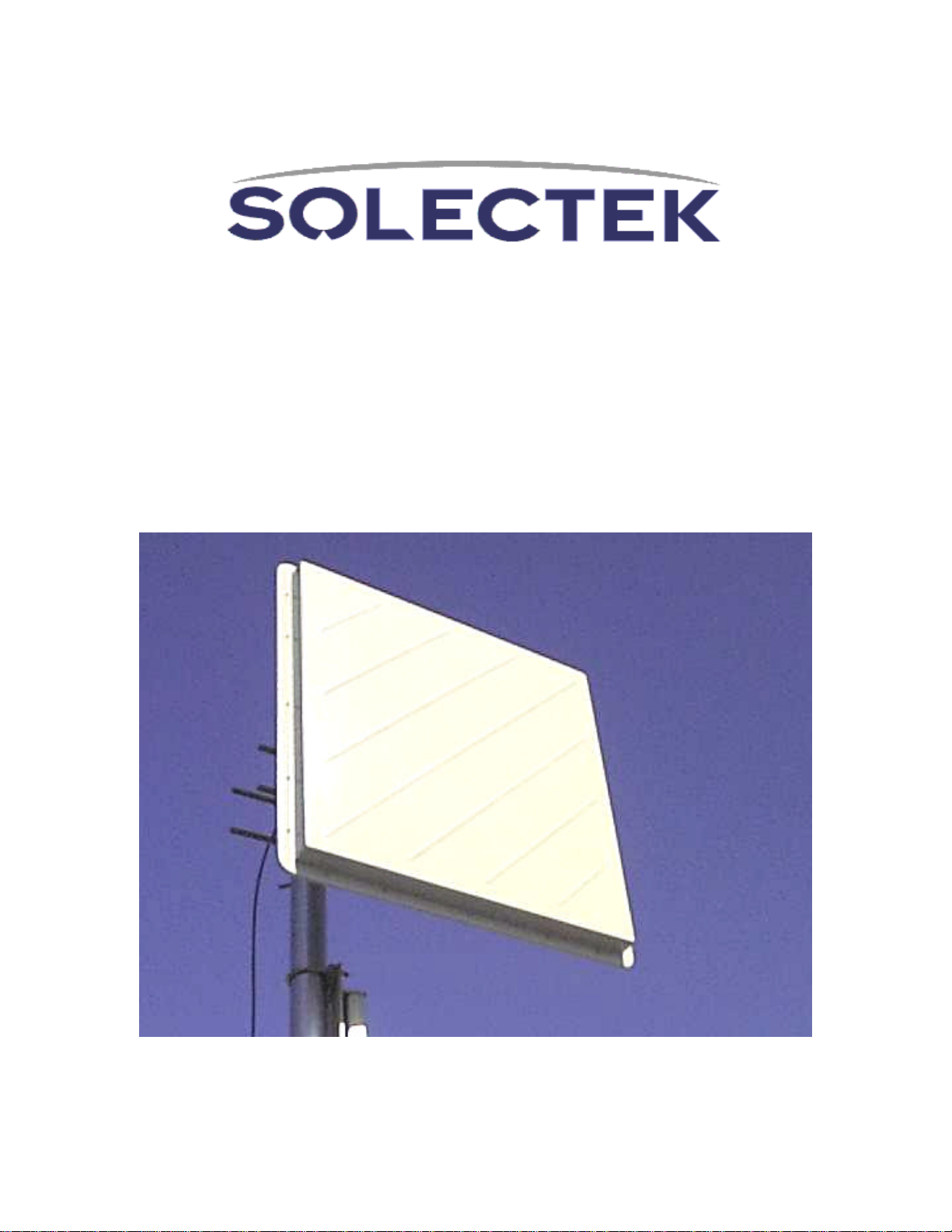
Unpack the PNL-22 antenna
and inventory all parts.
Contact your Solectek
Certified Reseller to resolve
any shortages.
This is the “Standard Mount”
used on the ANT-PNL-
22. The
single arm allows for full
elevation and azimuth
adjustment when mounted on
the mast. The optional
“Universal Mount” used on the
ANT-PNL-22-U is described
starting on Page 7. ODU
mounting and sealing of all
connectors are the same for
both the “Standard Mount” and
“Universal Mount”.
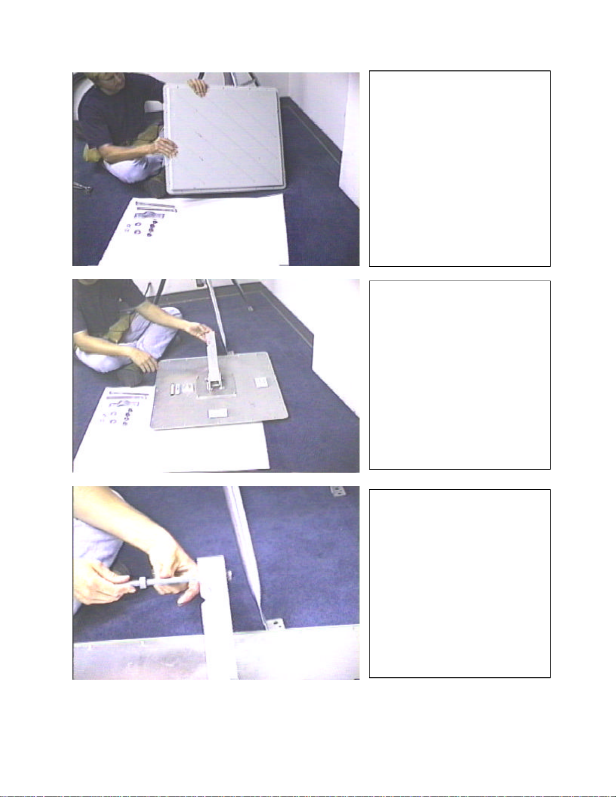
Locate the “V” cut in the
mounting arm. The “V” cut will
grip the mast when the
antenna is installed. Install the
long mast-clamp bolts as
shown. Use one nut to
securely mount the long bolts
to the mounting arm by turning
the nut all the way to the end
of the thread so it securely
holds the bolt in the mounting
arm.
Part #11243a Page 4of 9
Install the mast clamp strap as
shown. The strap makes a
channel with the “V” cut in the
mounting arm. The mast pipe
will pass through this channel.
Do not tighten the nuts.
Install the antenna and pre-
assembled bracket on the mast.
Tighten the two nuts so the
antenna is held securely to the
mast. Do not overtighten to the
point where the mounting strap is
deformed. These nuts will be
loosened later to swing the
antenna on the mast to adjust the
azimuth during antenna
alignment.
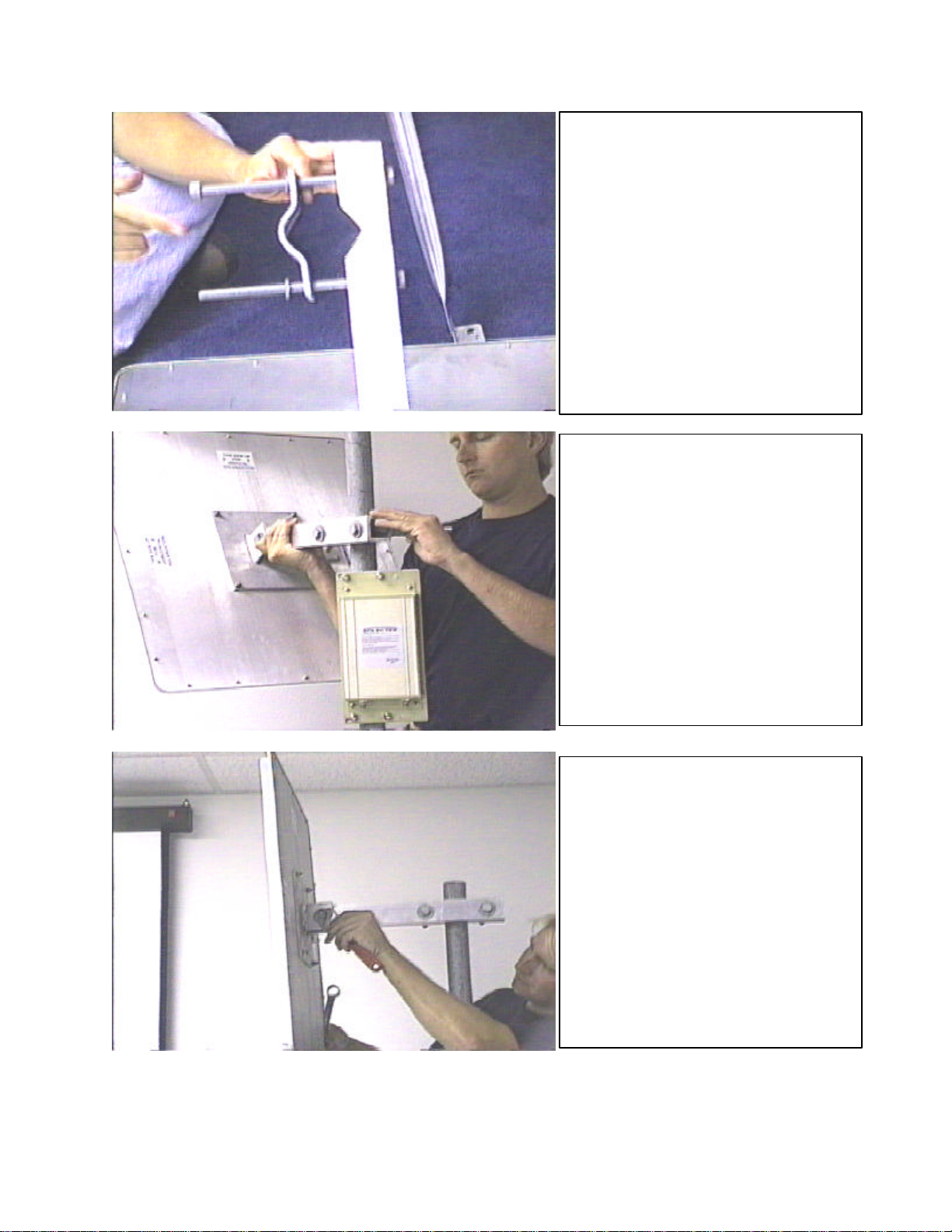
This is the “wrist joint” used to
adjust the elevation during
antenna alignment. In the vast
majority of installations, the
antenna will be mounted
vertically with reference to the
horizon. The antenna in this
photo is pointed slightly
downward. The antenna must be
adjusted to a true vertical position
before attempting the initial
antenna alighment.
Part #11243a Page 5of 9
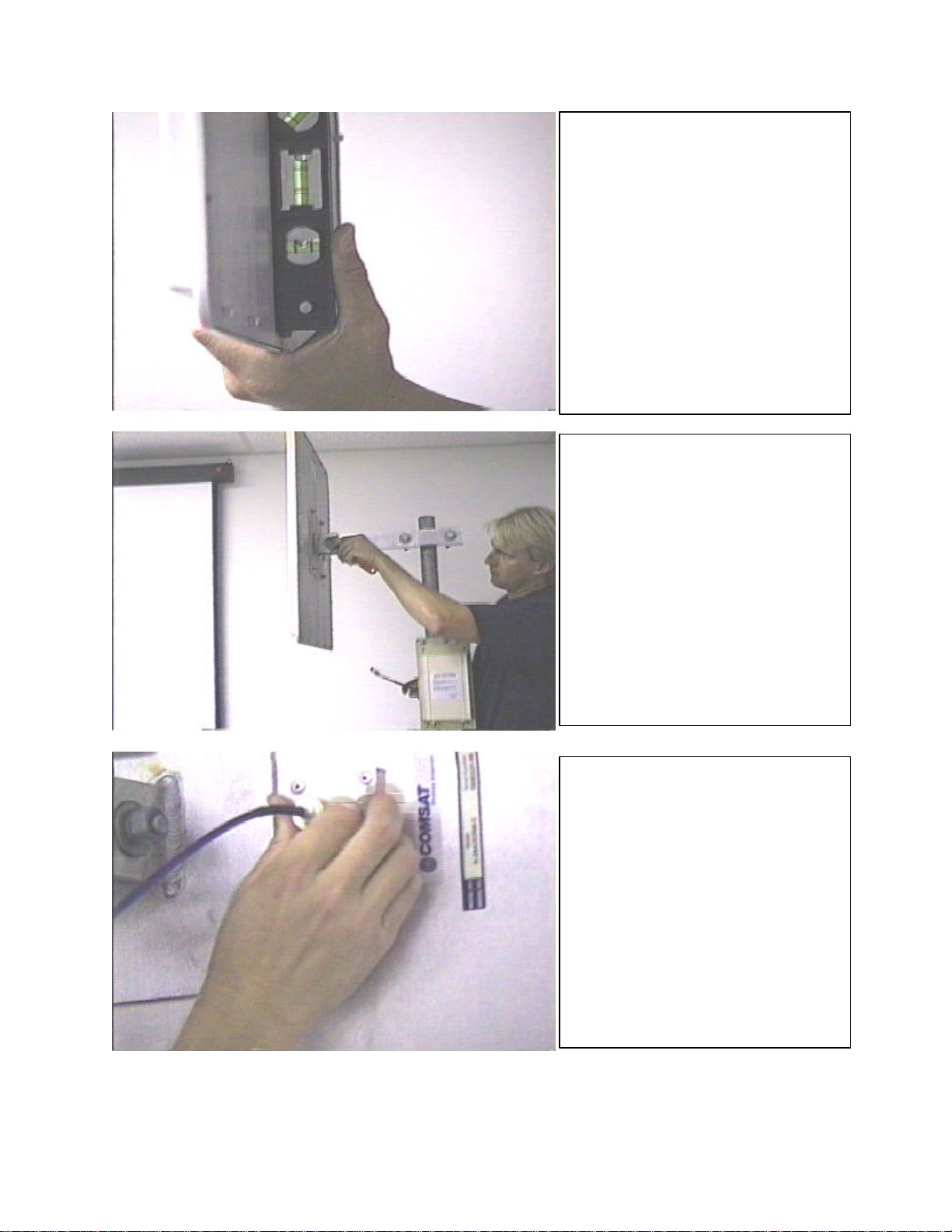
Use a bubble level (carpenter’s
level) to m
ake sure the antenna
is set to the vertical position
before attempting the initial
antenna alignment. It is usually
not necessary or desirable to
change this adjustment for
normal operation.
Once the antenna is checked
with a bubble level and set
vertically, tighten the “wrist bolt”
to lock it in place.
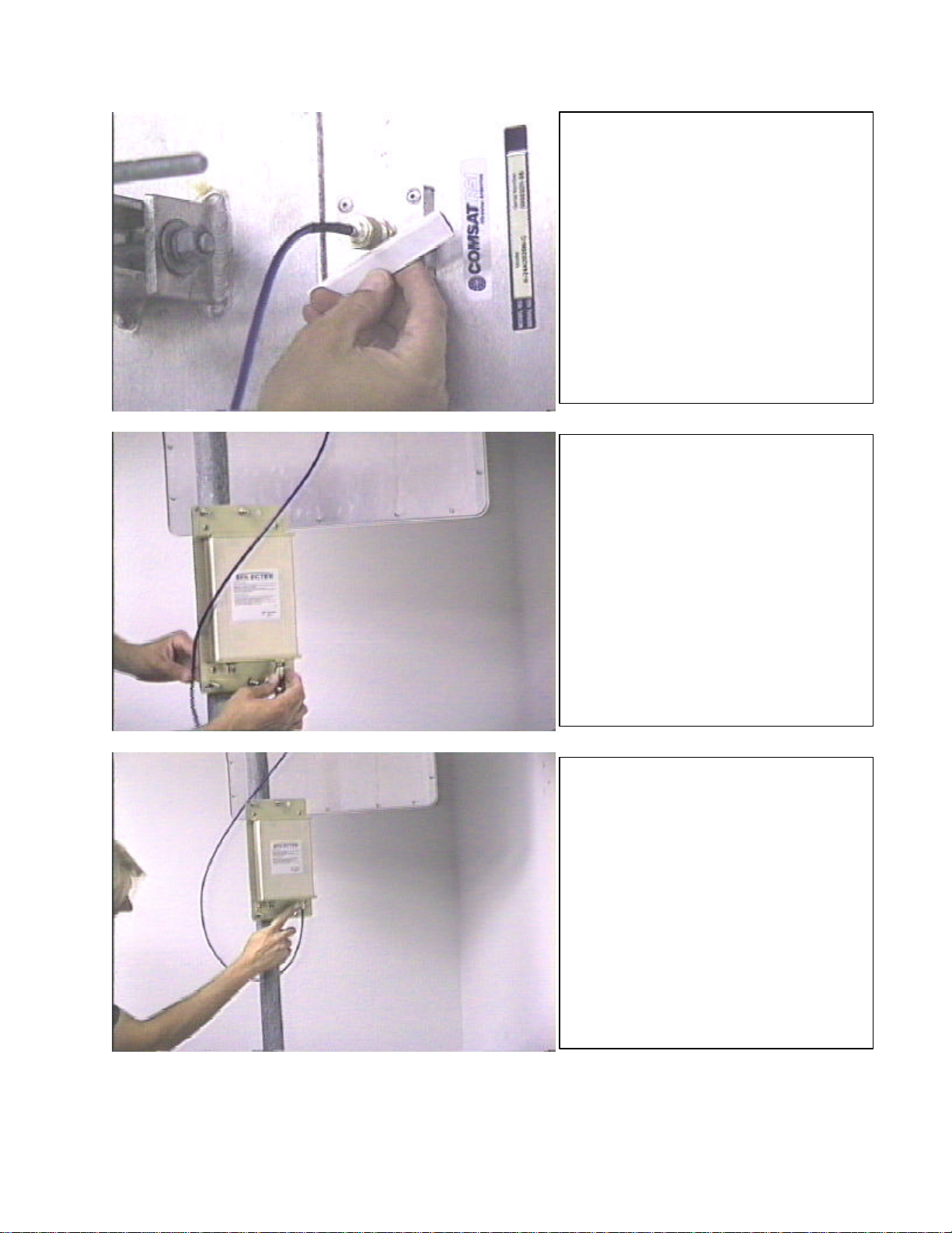
The PNL-
22 antenna is supplied
with a cable to attach the
antenna to the ODU (Outdoor
unit). The cable will fit only one
way, as the connectors are
different on each end. Finger
tighten the connector. Do not
use any tools, as you can easily
damage the connector.
Part #11243a Page 6of 9
Use the sealer strips supplied with
the antenna to seal the connector.
Peel the paper backing from the
strips and stretch the material
while winding it around the
connector. Be sure to cover all
exposed metal. This large (N-
type) connector will probably
require two strips for a proper,
weather tight seal. Use your
fingers to form the sealant against
the connector for a good seal.
Attach the antenna-to-ODU cable
to the ODU (Outdoor Unit). Finger
tighten the connector. No threads
should be visible when the
connector is properly tightened
and seated.
Use the black sealant material to
seal this connection after installi
ng
the antenna and ODU on the mast.
Part #11243a Page 7of 9
Stretch the black sealant
material while wrapping it
around t
he connector. It should
be possible to get a good seal
on this small (TNC-type)
connector with only one sealant
strip. If necessary, use a
second strip to ensure a
weather-tight seal.
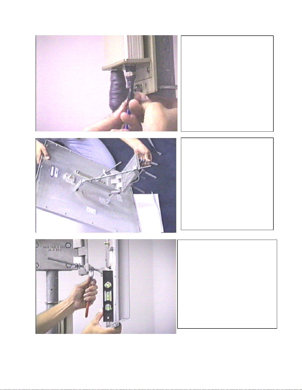
This is the optional “Universal
Mount”. This mount uses
threaded rods to adjust the
azimuth and elevation once the
antenna is permanently
mounted on the mast. Pre-
assemble the mount before
attempting to mount it on the
mast. This mount uses the
same mast straps and mounting
bolt as the “Standard Mount’.
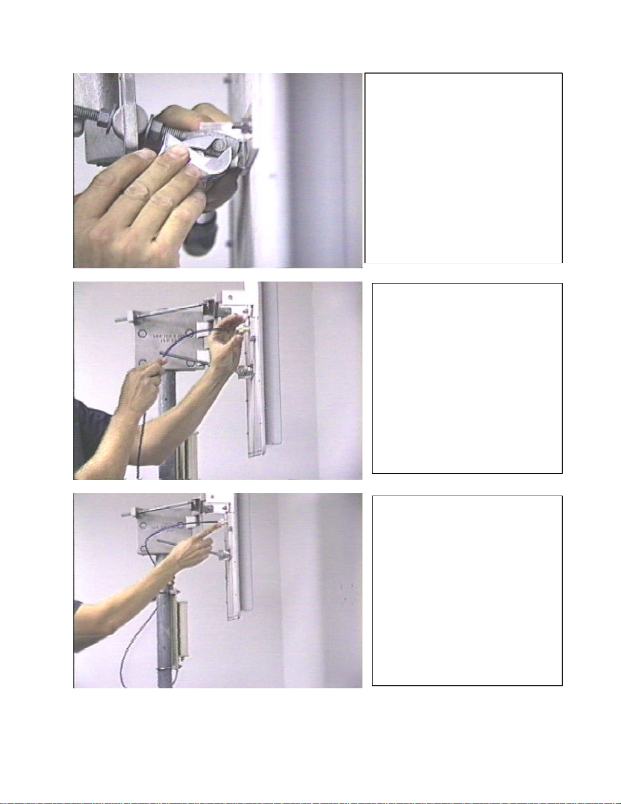
Use a bubble level (carpenter’s
level) to make sure the antenna is
set to a vertical position prior to
attempting the initial antenna
alignment. It is usually not
necessary or desirable to change
this adjustment for normal
operation. Note the use of the
wrench on the threaded rod to
change and lock/unlock the
elevation adjustment.
Part #11243a Page 8of 9
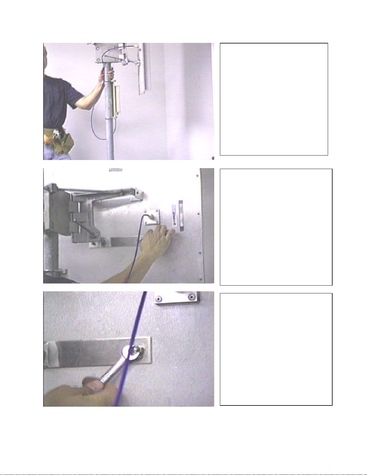
After setting the elevation with
the bubble level, lock the hinge
bolt and the lock nuts for a
permanent and secure elevation
setting.
Install the supplied antenna to
ODU cable. The cable cannot
be installed backwards, as the
connectors are different on
each end.
Seal the antenna connector
using the supplied sealan
t strips
(discussed previously in this
document).
Part #11243a Page 9of 9
** END**
Use Ty-Wraps or other
fastening material to hold the
antenna cables securely
against the mast.
All Solectek antennas are set to
vertical polarity at the factory.
To change the polarity, locate
the four small bolts on the back
of the antenna which fasten the
antenna to the mounting
bracket (either Standard or
Universal mount).
Carefully remove the four nuts
and washers which hold the
antenna to the mounting
bracket, remove the antenna
from the bracket, rotate the
antenna 90 degrees, and re-
fasten it to the mounting
bracket.

Domestic Warranty i99-028-0097-1
8/1/99
One Year Limited Warranty
For products purchased using
Solectek’s U.S. & Canada MSRP
Price List and installed in the
United States or Canada.
Effective August 1, 1999 Subject to the conditions and procedures set forth below during the warranty
period, Solectek will repair or replace, at Solectek's option, such Solectek
products or parts thereof which, on inspection by Solectek, are found to be
covered by the limited warranties set forth below. The warranty period for
new hardware products, which are listed on Solectek’s U.S. & Canada
MSRP Price List at time of purchase, is twelve months from the date of
shipment from Solectek. The warranty period for spare parts and R-part
numbers is ninety days from the date of shipment from Solectek.
If you think there is a problem or defect with your Solectek hardware
product:
nContact Solectek's Technical Support Department between 8:00 a.m.
and 5:00 p.m., Pacific Time at (858) 450-1220, or via fax at (858) 457-
Support Representative will discuss your problem to confirm the defect.
After business hours, please leave a voicemail or send an e-mail or fax.
A Technical Support Representative will respond to you the next
business day.
nIf warranty or return service is needed, you will receive a Return
Material Authorization (RMA) number. At no time should Solectek
products be sent back without a valid RMA number. Solectek accepts
no responsibility for unauthorized returns.
You agree to pay for shipping to Solectek. If the product is under
warranty, Solectek will pay for shipping of the repaired or
replacement product to you via ground transportation to your
location in the United States. For installations outside the
continental U.S., Solectek will pay for shipping via ground
transportation to the freight forwarder of your choice located in
the continental United States. Any other freight arrangements will
be at customer expense.
Solectek shall not be liable for any damage caused to the product
in transit. You acknowledge and agree that you will bear all risk
of loss or damage to the product while in transit.
Send return shipments to:
Solectek Corporation
6370 Nancy Ridge Drive, Suite 109
San Diego, CA 92121-3212
ATTN: RMA # _________
nPack products securely, to prevent damage in transit. Be sure the RMA
number is clearly visible on the outside of the return shipping carton.
nReturned Solectek products must include all other components from the
original package, including the hardware, cables, connectors, software
diskettes, and user manual(s) unless otherwise stipulated by Solectek.
nEnclose a copy of the original purchaser’s proof of purchase, if needed
to support warranty claim. (See details in LIMITATIONS section
below.)
After inspecting the failed unit, Solectek will repair or replace
materially defective parts or components. All products that are
replaced become the property of Solectek. If upon inspection by
Ce manuel convient aux modèles suivants
1
Table des matières
Manuels Antenne populaires d'autres marques

Alfa Network
Alfa Network APA-L01 Manuel utilisateur

Naval
Naval PR-422CA Manuel utilisateur

Feig Electronic
Feig Electronic ID ISC.ANTH200/200 Series Manuel utilisateur

TERK Technologies
TERK Technologies TV44 Manuel utilisateur

Directive Systems & Engineering
Directive Systems & Engineering DSE2324LYRMK Manuel utilisateur

HP
HP J8999A Manuel utilisateur


CommScope
CommScope CMAX-OMFX-43M-I53 Manuel utilisateur

Ramsey Electronics
Ramsey Electronics DAP25 Manuel utilisateur

COBHAM
COBHAM SAILOR 800 VSAT Manuel d'utilisation et d'entretien

Trango Systems
Trango Systems AD900-9 Manuel utilisateur

Steren
Steren ANT-100 Manuel utilisateur

Proxim
Proxim 5054-PA-23 Manuel utilisateur