SSA DIRECT PHOTOVOLTAIC OPEN LOOP MANUAL
5
5. COLLECTOR DIMENSIONS
Collector Gross Area (ft2) Dimensions (in) Transparent Area (ft2) Weight (lb)
SSA-21 20.87 35
3/16 x 85 3/16 19.22 74
SSA-24 23.81 35
3/16 x 97 3/16 21.99 84
SSA-26 25.35 47
3/16 x 77 3/16 23.65 90
SSA-28 27.97 47
3/16 x 85 3/16 26.16 99
SSA-32 31.91 47
3/16 x 97 3/16 29.93 113
SSA-40 39.79 47
3/16 x 121 3/16 37.47 153
Tested: TUV (DIN 4757, RAPPERSWILL, ONORM M7714, FSEC, SRCC, Metropolitan Dade County, Miami Test Lab
Table 2. Collector Dimensions for SSA series
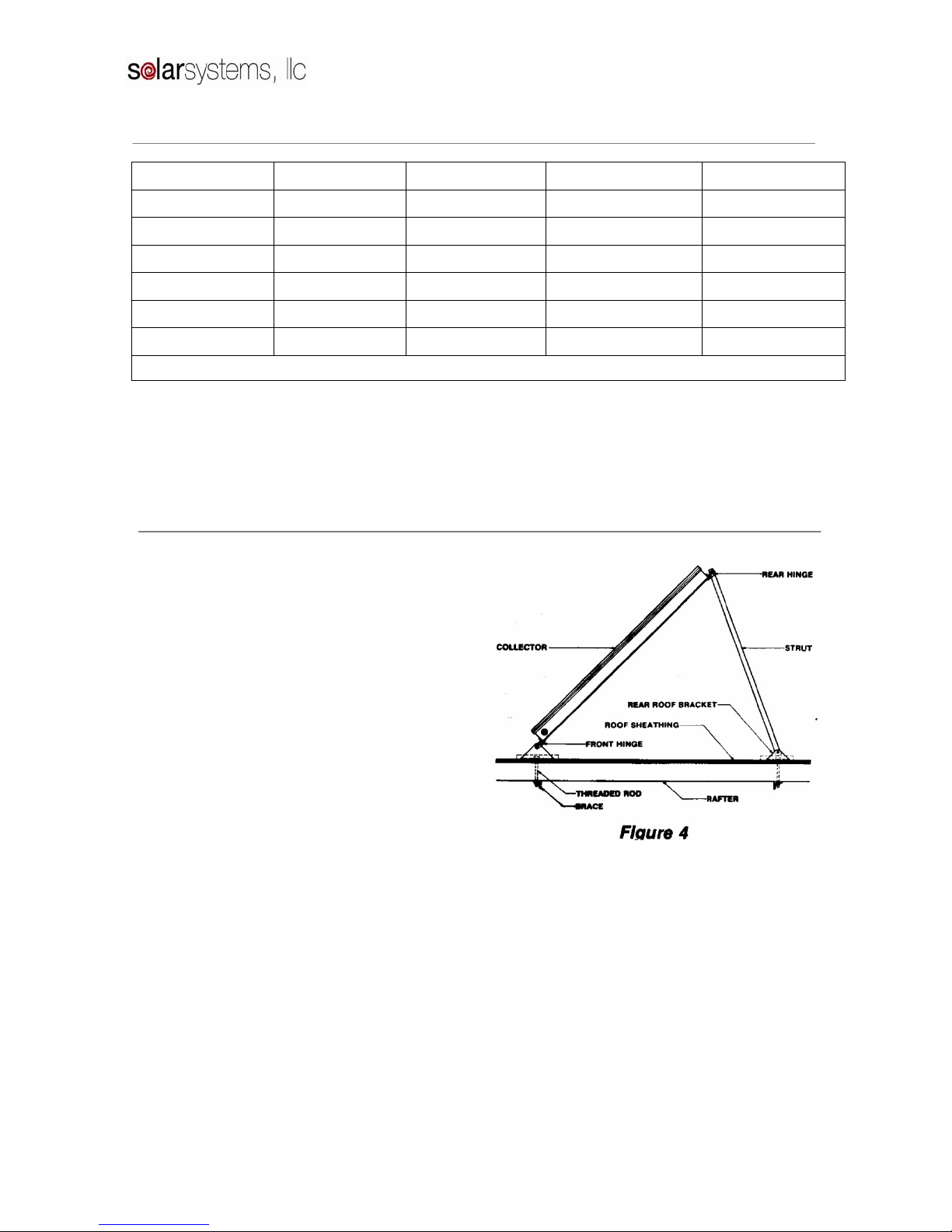
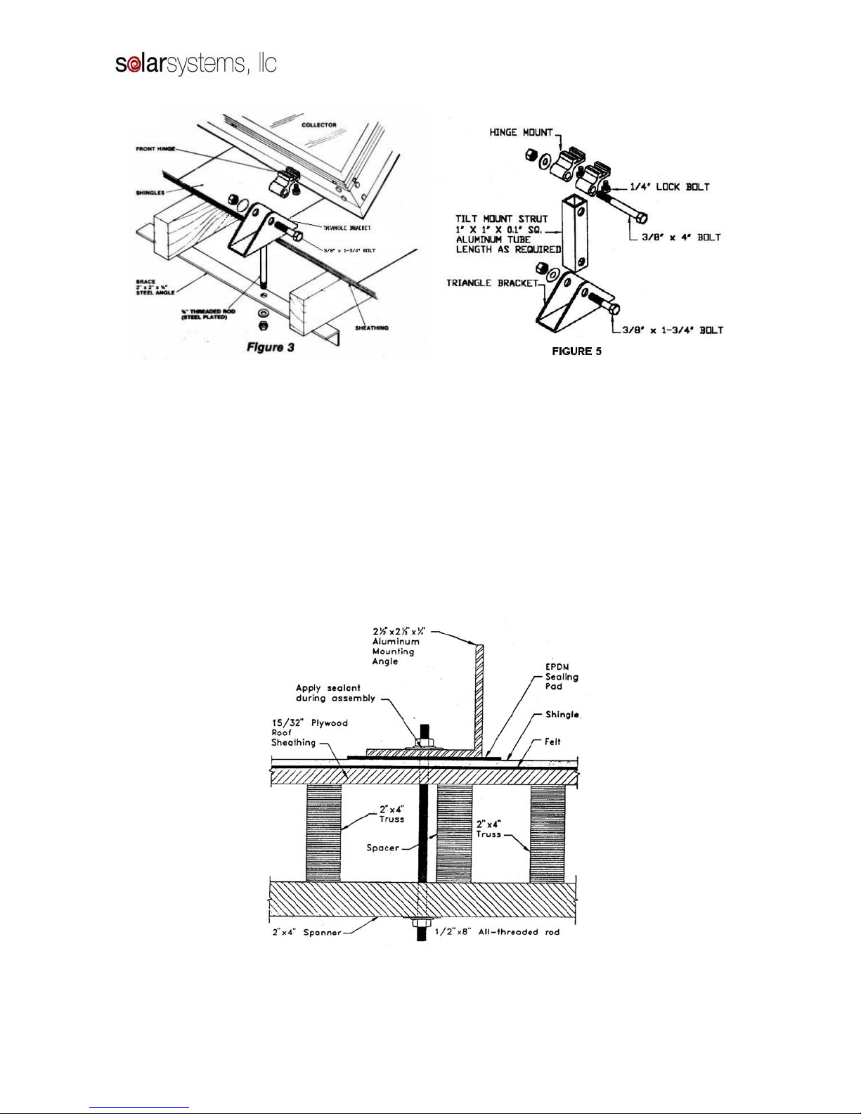
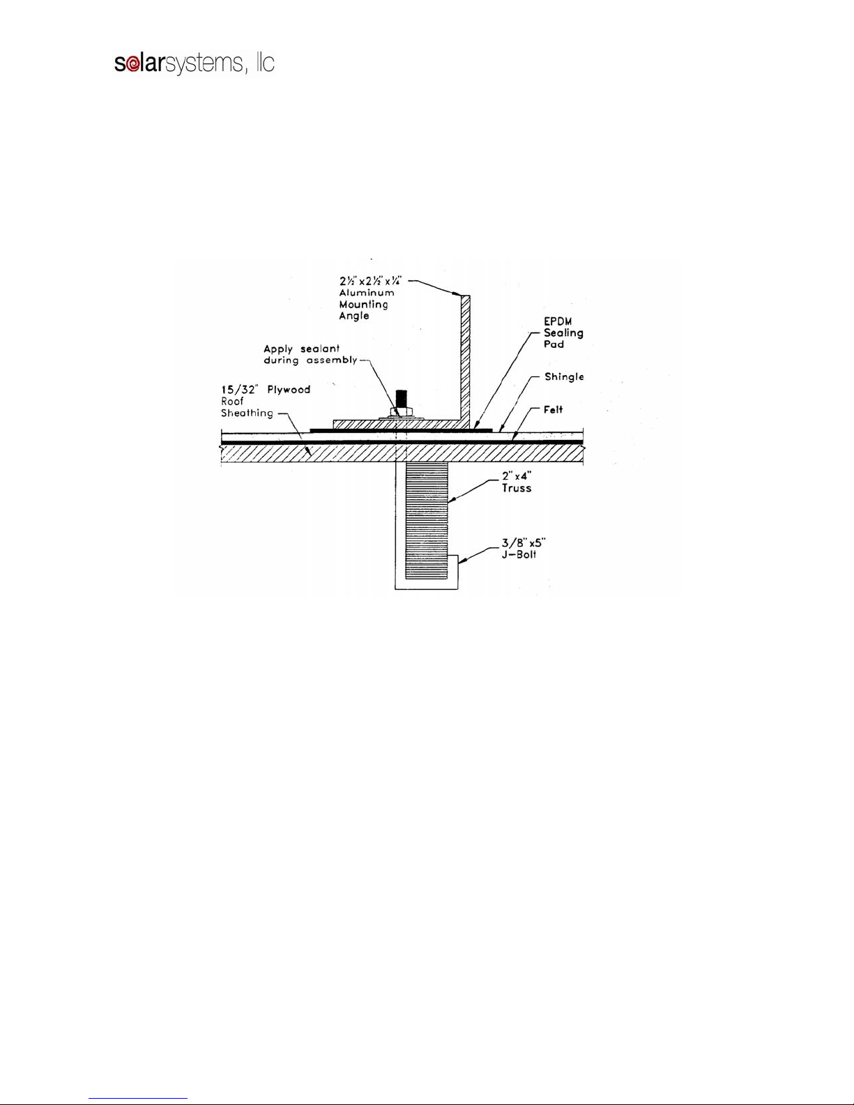
6. MOUNTING HARDWARE
Available with the System package is specially
designed mounting hardware to speed collector
installation. This hardware consists of four LOCK-
TIGHT hinge sets, four roof brackets, two rear
struts, and bolts (Figures 3, 4, and 5).
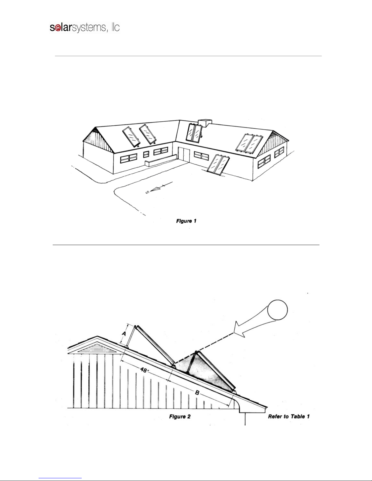
(a) After locating the mounting points from Table
1, the mounting bracket holes should be drilled.
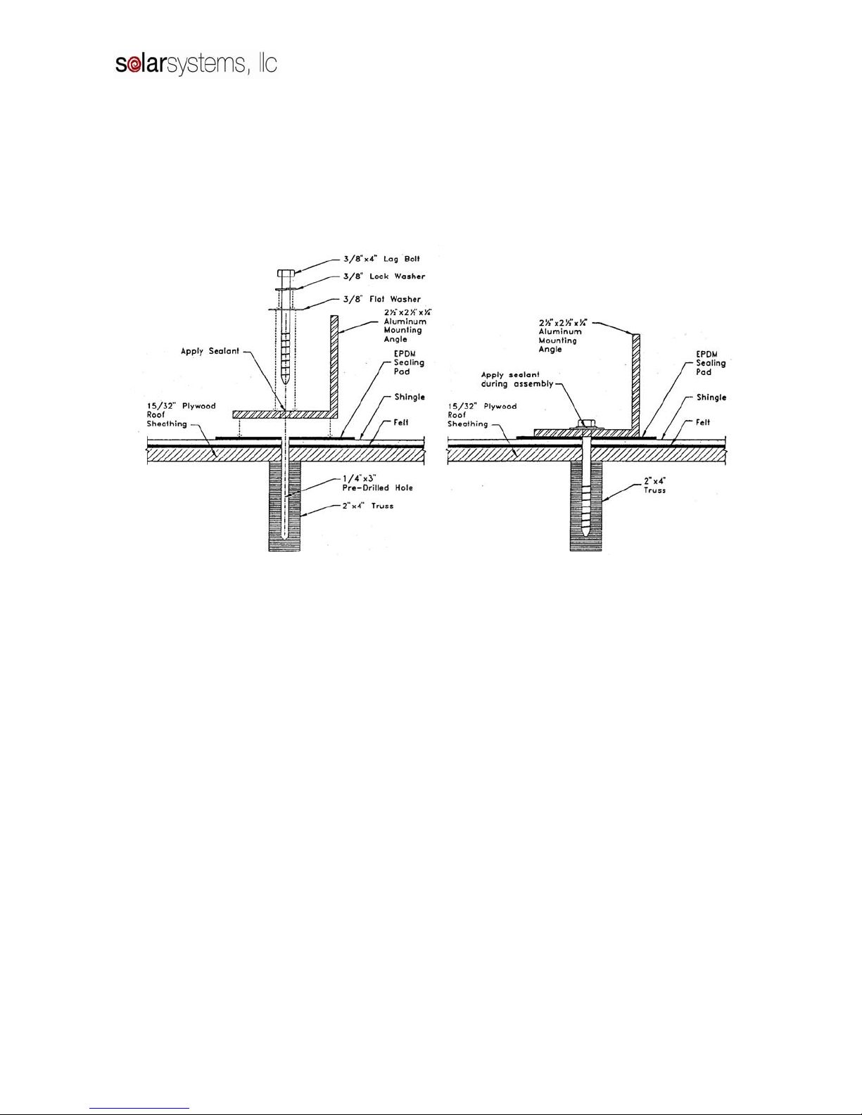
(b) A heavy coating of sealant should be applied to
the bottom of the flashing plate, which should
fit flat against the roof. It is necessary for the
plate to slide under the above shingles to insure
proper drainage of water.
(c) The bottom of the roof bracket and the area
around the threaded rod should also be
thoroughly coated with tar sealant. When the
bracket is set in place, alignment with the
collector hinges is necessary before final
tightening of the nuts. This should be
completed before the sealant has time to set.
(d) The threaded rod is fastened through a 2’ x 6”
wood or 2” x 2” x ¼” steel angle bracket under
the roof as shown.
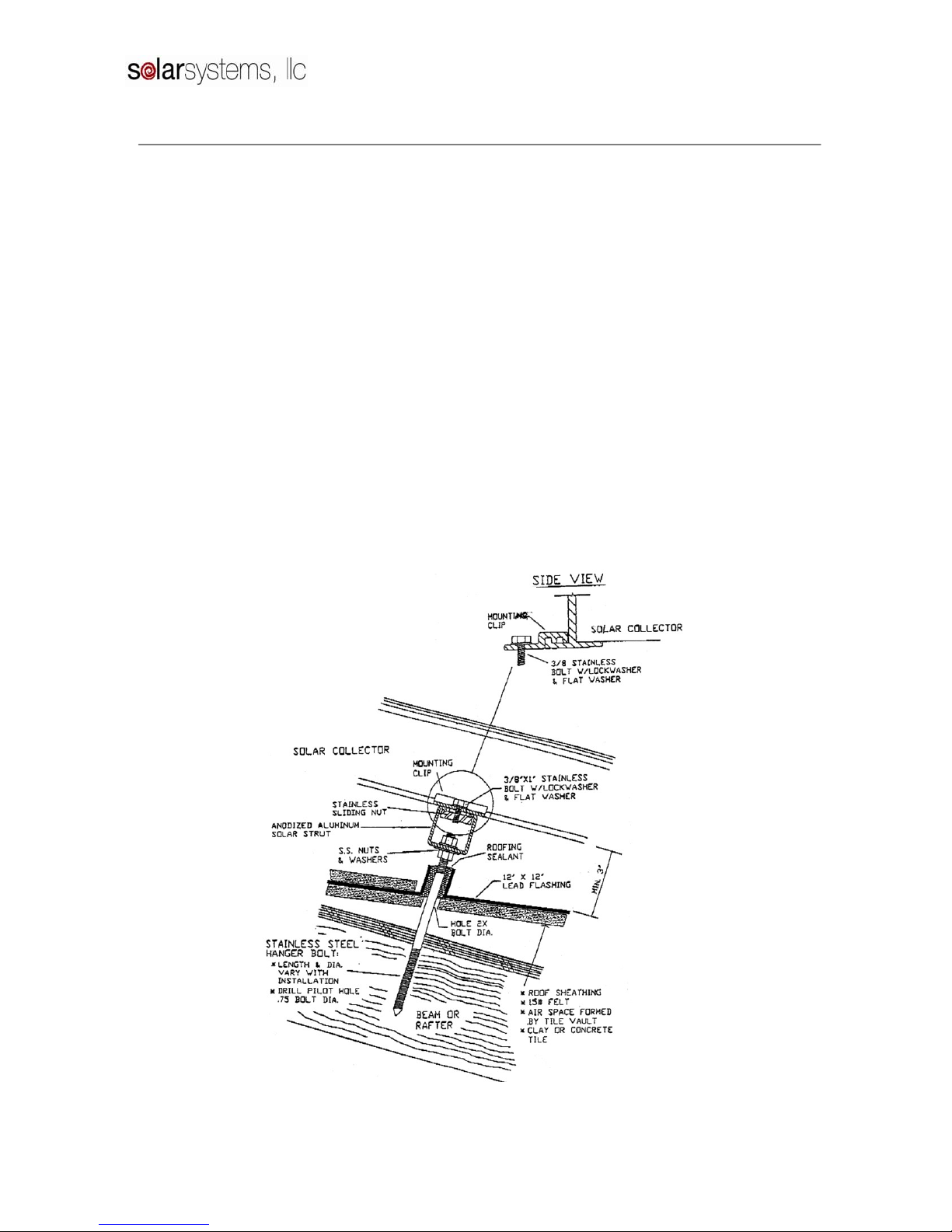
(e) The rear struts should be cut and drilled to
conform to Table 1. All bolts should be
tightened securely. A stainless steel washer
should be placed where the threaded rod passes
through the aluminum bracket.
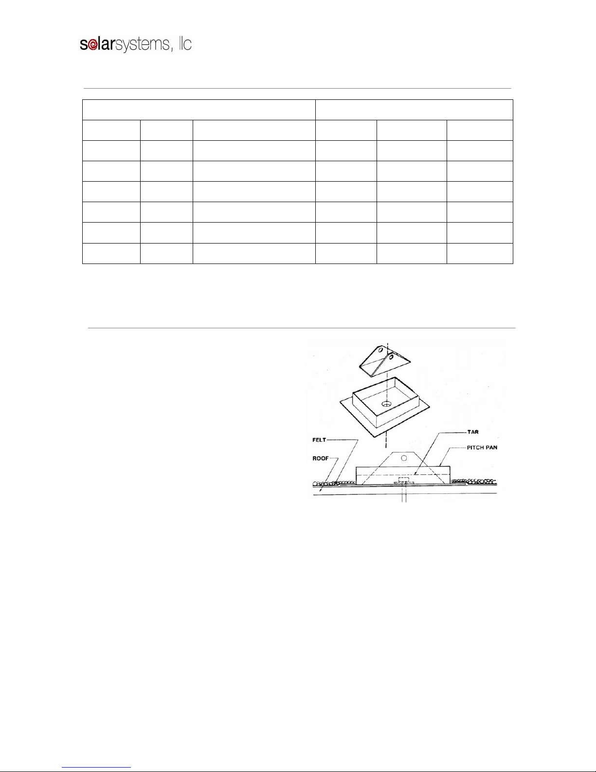
It is very important that the penetrations through the
roof be well sealed. It should be carefully checked
that all bolts are coated with tar and that no leaks
are possible.