Solarsol SSP27 Manuel utilisateur
User Manual
Photovoltaic Modules
SSP27

User Manual
Contents
Module Size ................................................................................................................................................................4
Safety instructions......................................................................................................................................................5
Installation guidelines.................................................................................................................................................7
Mechanical installation. .............................................................................................................................................8
Electrical installation. .............................................................................................................................................. 10
Grounding................................................................................................................................................................ 12
Maintenance and care............................................................................................................................................. 15
Transport and storage. ............................................................................................................................................ 15

General information
Thank you for buying SOLARSOL!
Please read the following instructions carefully before transporting, installing or operating SOLARSOL photovoltaic
modules.
This manual contains important information concerning the safety, care and maintenance of SOLARSOL
photovoltaic modules.
The installation and operation of photovoltaic modules requires a high degree of skills and experience, so it must
be performed ONLY BY PROFESSIONALS.
Each module has three labels that identifies the serial number of the product. The label located on the back of the
solar module contains important information about the: Maximum Power, Electric Tolerance, Open Circuit
Voltage (Voc), Short Circuit Current (Isc), Maximum Power Current (Imp) and Maximum Power Voltage (Vmp) , all
of them measured under STC conditions (25 ° C, 1000 W/m2, 1.5 ATM).
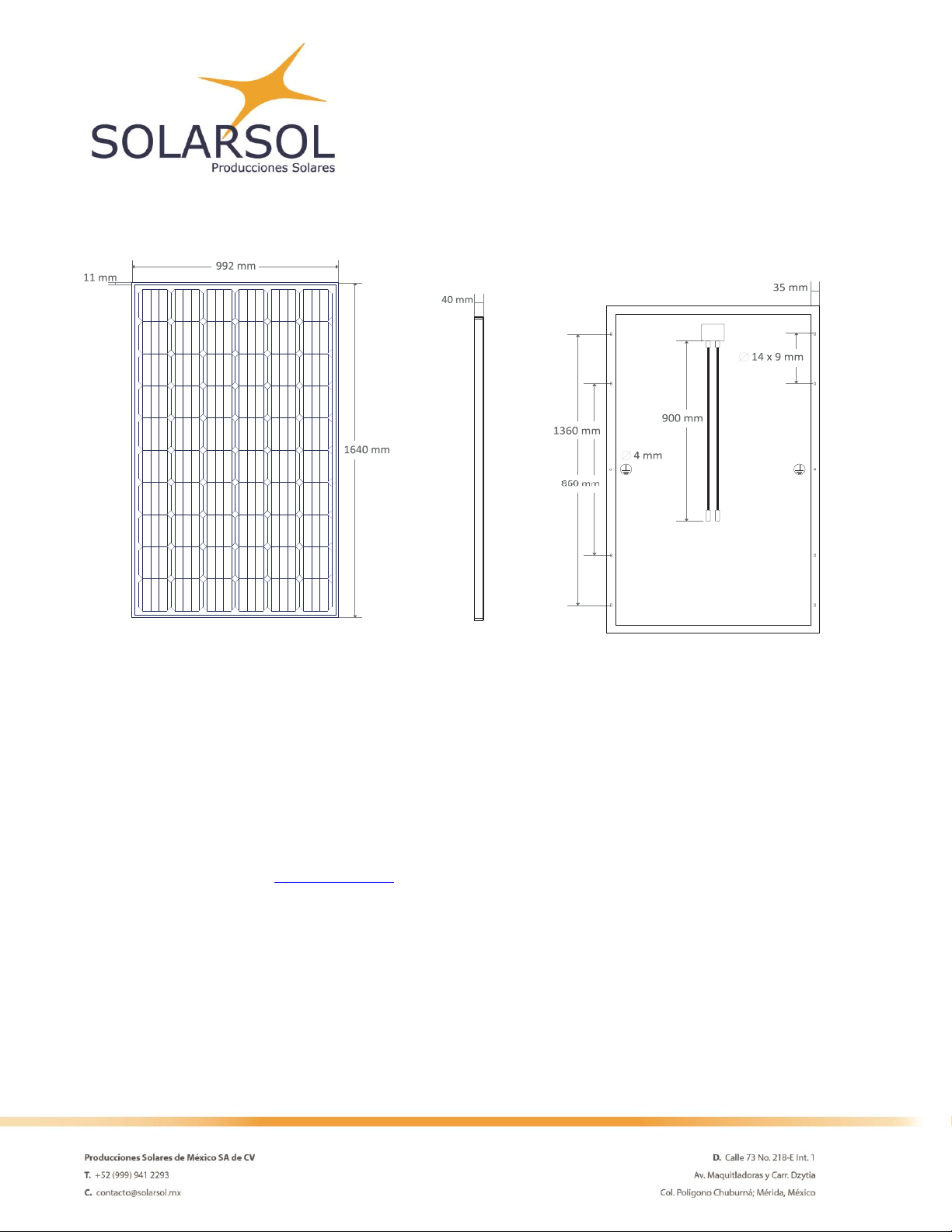
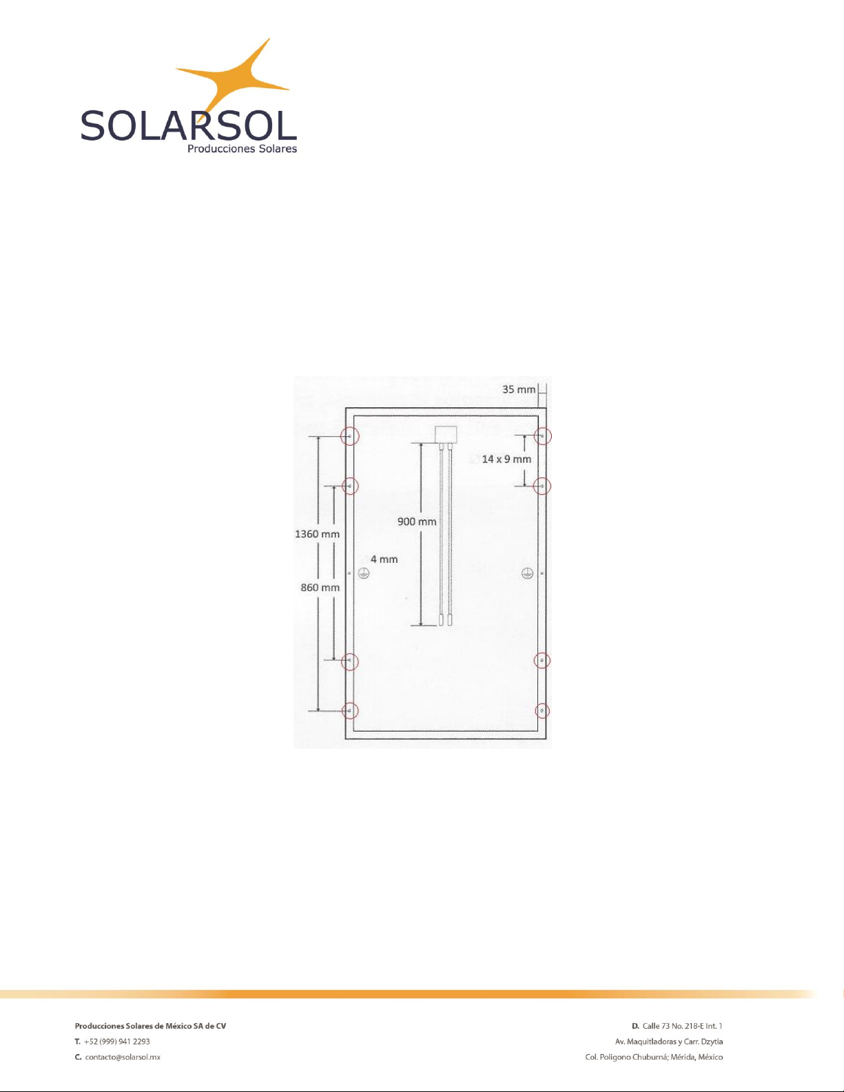
SOLARSOL photovoltaic modules have the following dimensions: 1640 mm tall, 990 mm wide and a thickness of
40 mm (See figure 1). Each module has a junction box located at the back of the module with 900 mm long wires
with MC4 connectors. The aluminum frame that protects the module, has eight holes, six of them for the mounted
and the others two must be use only to ground the module.

Safety instructions.
IMPORTANT
Before installing, wiring or handling the photovoltaic modules, please read the
instructions below.
The wrong installation of photovoltaic devices can result in serious injuries.
All installation work must obey the standards established by international, national and local regulations.
Before installation, remove all metallic object and jewelry.
Safety equipment must be worn at all time during the installation.
For your safety use insulated tools and gloves.
Do not allow unauthorized people access to the installation area.
Photovoltaic systems can be installed on roofs or high ground, however, modules should be installed only on
surfaces capable of supporting the additional weight of the panels.
The modules must be anchored to the ceilings by a formal structure result of a complete load analysis.
Do not install photovoltaic modules near flammable substances, gases or vapors.
The fire rating of this module is valid only when mounted in the manner specified in the
mechanical mounting instructions.
Work EXCLUSIVELY in dry conditions. For your safety, do not install or manipulate the
photovoltaic modules under adverse weather conditions.
Reflection caused by snow or water can increase sunlight, raising the power
generated by the solar modules. Additionally, low temperatures can boost the panel power.
Photovoltaic modules produce electricity when exposed to light, which can lead to electric
shocks or burns. They must always be handled with extreme caution.
Even in low light conditions the photovoltaic modules are able to generate a voltage equal
to VOC in STC, do not concentrated artificially sunlight on the module or panel.
Do not install or use broken modules. Contact with the surface of the modules can cause electric shock if the front
glass is broken or the backsheet perforated.
A module with exposed conductivity parts is considered with the requirements of UL 1703 only when it is
electrically grounded in accordance with the instructions presented below and the requirements of the National
Electrical Code.
Modules and module frames must not be drilled, nailed or welded under any circumstances.
Do not disassemble the module or remove any of its parts. The photovoltaic modules do not contain any repairable
parts.
Any module without a frame shall not be considered to comply with the requirements of UL 1703 unless the
module is mounted with hardware that has been tested and evaluated with the module under this standard or by
a field inspection certifying that the installed module complies with the requirements of UL 1703.
Do not connect or disconnect modules when the modules current or an external source is present.
Installation guidelines.
PHOTOVOLTAIC MODULES MUST BE INSTALLED ONLY BY PROFESSIONALS.
The modules must be mounted on resistant structures. The structures must be resistant to corrosion. Before
proceeding with the installation, SOALRSOL recommends to perform a structural stability analysis of the surface
where the modules will be mounted.
The installation structures can be located on roofs or even on the ground.
Install the photovoltaic modules avoiding shadow conditions produced by nearby bodies, such as trees, water
tanks or antennas. Constant shadow conditions reduce the performance of the modules and affect their life time.
Do not install the modules near fountains or pools to avid constantly exposure to water.
Position the front of the solar modules so that it faces the terrestrial equator.
Select the correct inclination angle according to local conditions.
Mechanical installation.
The module is considered to be in compliance with UL 1703 only when the module is mounted in the manner
specified by the mounting instructions below.
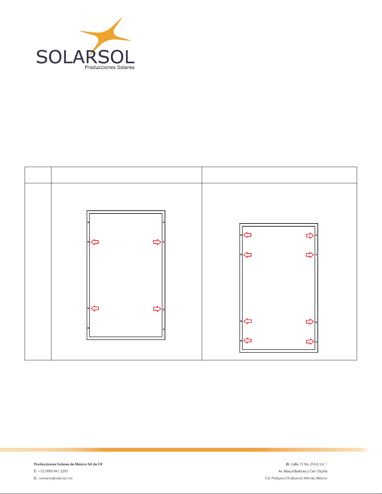
SOLARSOL photovoltaic modules can be installed using the holes found in the aluminum frame (See Figure 2).
They can also be installed using a clamp system.
For any installation method, the photovoltaic modules must be insured in at least 4 different points.
Figure 2. Encircled in red, the installation holes in the module’s frame.
Modules can be installed in landscape or portrait orientation.
The Fire Class Rating of the module in a mounting system in combination with roof covering complete with the
requirements to archive a class C.
To maintain the Fire Class Rating C, the system should have a minimum 10 cm gap between the module frame
and the mounting surface and it must be installed ONLY on surfaces resistant to fire.
SOLARSOL recommends the following installation method for photovoltaic modules:
To do so, it’s necessary a M4 or #10 SS Screw, M4 SS Flat washer, M4 SS Cup washer, M4 SS Toothed washer, M4
SS Nut. Insert the flat washer into the screw and then insert the cup washer before you place it in the mounting
holes. Secure the screw to the aluminum frame using the toothed washer and a backing nut on the end of the
screw.
Normal level of load condition
High level of load condition
Screw fastening to assembly holes
Applies to most of the environmental conditions.
Use four mounting holes.
Applies to harsher environmental conditions such as
storms
Use eight mounting holes.
SOLARSOL DOES NOT INSTALL PHOTOVOLTAIC MODULES. However, you can contact us and we will gladly
communicate you with one of our installers. For further information, email us to: [email protected].
Electrical installation.
Voltage
Current
Power
Open circuit Voltage
38.16 V
Short Circuit Current
8.86 A
Maximum
Power
270 W
Operating Voltage
32.34 V
Current at rated Operating
Voltage
8.36 A
Maximum System voltage
600 V
The electrical characteristics are within ±3 percent of the indicated values of ISC, VOC and Pmax under standard
test conditions (irradiance of 1000 W/m2, AM 1.5 spectrum and a cell temperature of 25°C (77°F)).
Do not install broken modules. Make sure that Jboxes and wires are clean and dry.
SOLARSOL photovoltaic modules are equipped with junction boxes JMTH model JM13 designed to be easily
interconnected in series for their well-connected cable and the connector with IP67. Three By-pass diodes are
located at the interior of the Jbox for overcurrent protection. Each module has two single conductor wires pre-
wired inside the junction box. In addition, the connector conductor wires are equipped with special MC4
connectors for photovoltaic equipment.
The connector plugs are labeled with their respective polarity (red positive and black negative). Check the polarity
when interconnecting the modules and the inverter. A wrong polarity connection can permanently damage all
electronic components of the system.
SOALRSOL recommends USE ONLY dedicated solar cable (6-12 AWG), with temperature resistance between -40°C
to 90°C.
Protect the wires by securing them with clips or tapes to the frames. Avoid squash them or put them under
pressure.
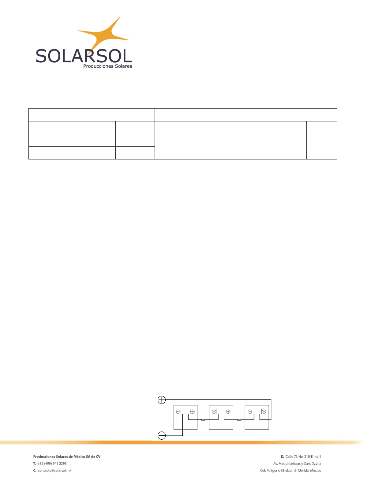
The following diagram shows 3 different ways of interconnect the solar modules.
Series wiring
Table des matières


