Solaris SoLED W840 Manuel utilisateur

V4.1
SoLED W840
USER MANUAL
PRELIMINARY

SoLED W840 User Manual Version 4.1 051915 PRELIMILARY 2
TABLE OF CONTENTS
1. INTRODUCTION ................................................................................................................................... 3
PRODUCT OVERVIEW ...............................................................................................................................................3
WHAT IS INCLUDED ..................................................................................................................................................3
UNPACKING INSTRUCTIONS.......................................................................................................................................3
POWER REQUIREMENTS...........................................................................................................................................3
FREQUENCY SETTING ..............................................................................................................................................3
SAFETY INSTRUCTIONS.............................................................................................................................................4
2. SETUP ................................................................................................................................................... 4
FUSE REPLACEMENT................................................................................................................................................4
FIXTURE LINKING.....................................................................................................................................................5
DMX DATA CABLE...................................................................................................................................................5
CABLE /CONNECTORS .............................................................................................................................................5
3-PIN TO 5-PIN CONVERSION CHART..........................................................................................................................6
SETTING UP A DMX SERIAL DATA LINK .....................................................................................................................6
FIXTURE MOUNTING /RIGGING..................................................................................................................................7
3. OPERATING INSTRUCTIONS ............................................................................................................. 7
CONTROL PANEL NAVIGATION...................................................................................................................................7
MENU MAP .............................................................................................................................................................9
FUNCTION DESCRIPTION......................................................................................................................................... 10
STROBE MODES ....................................................................................................................................................11
EFFECTS DESCRIPTIONS ........................................................................................................................................12
MANUAL MODE......................................................................................................................................................13
MEASURE .............................................................................................................................................................15
THERMOMETER ..................................................................................................................................................... 16
4. APPENDIX .......................................................................................................................................... 17
BASICS OF DMX CONTROL.....................................................................................................................................17
GENERAL MAINTENANCE ........................................................................................................................................17
LIMITED WARRANTY............................................................................................................................................... 18
RETURN PROCEDURE ............................................................................................................................................ 18
CONTACT INFORMATION .........................................................................................................................................19
TECHNICAL SPECIFICATION.....................................................................................................................................20

SoLED W840 User Manual Version 4.1 051915 PRELIMILARY 3
1. INTRODUCTION
PRODUCT OVERVIEW
The Solaris LED SoLED W840 white LED strobe offers the same look and feel as xenon strobes at a fraction of
the power consumption. Using high-intensity Cree® LEDs, the SoLED provides ultra-bright whites with 92,000
lumen peak output. Compact and lightweight, the SoLED is very portable and hides well in any application.
Ultra-bright – 840 Watts of brilliant white output, 92,000lm peak output
Compact and lightweight – Fits almost anywhere
Easy to use – Same control modes and personalities as other popular strobes
DMX512 with RDM – Easy to control plus continual operational feedback
LED design – Longer life than xenon lamps for reliability and long-term cost savings
Built-in yoke – Application and mounting flexibility
Fan-free – Quiet operation, perfect for theatre, film, and TV use
WHAT IS INCLUDED
1x Solaris LED W840 fixture
1x Power cable
1x User Manual
UNPACKING INSTRUCTIONS
Upon receipt of the fixture, carefully unpack the carton and check the contents to ensure that all parts are
present and in good condition. Notify the shipper immediately and retain packing material for inspection if any
parts appear to be damaged from shipping or if the carton itself shows signs of mishandling. Save the carton
and all packing materials. In the event that a fixture must be returned to the factory, it is important that the fixture
be returned in the original factory box and packing.
POWER REQUIREMENTS
Before powering the unit, make sure the line voltage is within the range of accepted voltages. This fixture
accommodates 100-240VAC, 50/60Hz. All fixtures must be powered directly from a switched circuit and cannot
be operated with a rheostat (variable resistor) or dimmer circuit, even if the rheostat or dimmer channel is used
solely as a 0-100% switch.
When powered up, SoLED performs a preprogrammed internal test. On initial power-up the factory default DMX
address appears on the display screen and SoLED is ready for operation. After initial power-up, the last-saved
DMX address will appear.
FREQUENCY SETTING
Depending on location, change the Default Frequency setting to match the mains power (e.g., US and Canada
should be set at 60Hz). Proper frequency setting will ensure minimum amount of visible artifacts when using
Solaris LED on camera.
SoLED W840 User Manual Version 4.1 051915 PRELIMILARY 4
SAFETY INSTRUCTIONS
Please keep this Operation Manual for future reference. If unit is sold to another user, make sure they also
receive this instruction booklet.
Ensure fixture is connected to proper voltage, and that line voltage is not higher than that stated on the
fixture.
Make sure there are no flammable materials close to the unit while operating.
Always disconnect from the power source before servicing or fuse replacement. Always use the fuse
specified in this manual.
Always use a safety cable when hanging fixture overhead.
Maximum ambient temperature (Ta) is 40°C (104°F). Do not operate fixture at temperatures above this
rating.
In the event of a serious operating problem, stop using the unit immediately. Repairs must be carried out by
trained, authorized personnel. Contact the nearest authorized technical assistance center. Only OEM spare
parts should be used.
Do not connect the device to a dimmer pack.
Make sure power cord is never crimped or damaged.
Never disconnect power cord by pulling or tugging on the cord.
Avoid direct eye exposure to the light source during operation.
Caution! There are no user serviceable parts inside the unit. Do not open the housing or attempt any
repairs yourself. In the unlikely event your unit may require service, please contact your distributor.
2. SETUP
FUSE REPLACEMENT
SoLED uses a 12A 250V slow-blow fuse. To replace fuse:
1. With a screwdriver turn the fuse cap counter-clockwise to remove fuse cap with fuse.
2. Replace fuse attached to fuse cap.
3. Reinsert fuse cap with new fuse and tighten clockwise.
Please read these instructions carefully. This user guide
contains important information about the installation, usage and
maintenance of this fixture.
Disconnect the power cord before replacing the
fuse. Always replace with the correct fuse type.

SoLED W840 User Manual Version 4.1 051915 PRELIMILARY 5
FIXTURE LINKING
A DMX data link is needed to operate one or more fixtures with a DMX-512 lighting console. The combined
number of channels required by all of the fixtures on the DMX data link will determine the number of fixtures the
DMX data link can support. Maximum recommended DMX data link distance between fixtures: 984 ft. (300
meters).
Important: Fixtures on a DMX data link must be daisy-chained in one single line. To comply with the
EIA-485 standard, no more than 32 devices should be connected on one data link. Connecting more
than 32 fixtures on one serial data link without the use of a DMX optically-isolated splitter may result in
deterioration of the digital DMX signal.
DMX DATA CABLE
Use a ProPlex® DMX cable or equivalent which meets the specifications for EIA RS-485 applications. Standard
microphone cables cannot transmit DMX data reliably over long distances. The data cable must have the
following characteristics:
2-conductor twisted pair plus a shield
Max. capacitance between conductors – 30 pF/ft.
Max. capacitance between conductor and shield – 55 pF/ft.
Max. resistance of 20 ohms / 1000 ft.
Nominal impedance 100-140 ohms
CABLE / CONNECTORS
Cabling must have a male XLR connector on one end and a female XLR connector on the other end.
DMX connector configuration
CAUTION: Do not allow contact between the common and the fixture’s chassis ground. Grounding the
common can cause a ground loop, and your fixture may perform erratically. Test cables with an ohm
meter to verify correct polarity and to make sure the pins are not grounded or shorted to the shield or
each other.

SoLED W840 User Manual Version 4.1 051915 PRELIMILARY 6
3-PIN TO 5-PIN CONVERSION CHART
If using a console with a 3-pin DMX output connector, a 3-pin to 5-pin adapter is needed. The chart below details
a proper cable conversion:
3-PIN TO 5-PIN CONVERSION CHART
Conductor
3 Pin Female (output)
5 Pin Male (Input)
Ground / Shield
Pin 1
Pin 1
Data ( - ) signal
Pin 2
Pin 2
Data ( + ) signal
Pin 3
Pin 3
Do not use
Do not use
Do not use
Do not use
SETTING UP A DMX SERIAL DATA LINK
1. Connect the (male) 5-pin connector side of the DMX cable to the output (female) 5-pin connector of the DMX
console.
2. Connect the opposite end of the cable (female) to the input connector of the fixture consisting of a (male) 5-pin
connector.
3. Proceed to connect from the fixture output as stated above to the input of the following fixture and so on.
4. Continue linking until the last fixture is connected in your DMX chain.

SoLED W840 User Manual Version 4.1 051915 PRELIMILARY 7
FIXTURE MOUNTING / RIGGING
Orientation
Solaris LED fixtures may be mounted in any position. Always make sure there is adequate room for ventilation.
Do not obstruct the unit’s vents.
Support Stand
Always use a professional stand rated to support weight greater than the SoLED weight (4.77 lb. / 2.15
kg). Attach a TVMP spigot to the yoke of the SoLED and mount on the stand.
Rigging – Always consult a qualified rigging specialist before suspending any fixture
overhead.
Use ProBurger® couplers or equivalent C- or O-type clamps for attaching to truss. Do not
obstruct vents. Adjust the fixture angle by loosening both knobs and tilting the fixture as
needed. After establishing the desired position, retighten both knobs.
Always use safety cables!
When selecting installation location, consider routine maintenance.
Never mount fixture where it will be exposed to moisture, high humidity, extreme
temperatures, or restricted ventilation.
3. OPERATING INSTRUCTIONS
CONTROL PANEL NAVIGATION
Access control panel functions via four control panel buttons surrounding the LCD display. Buttons are indicated
by a concentric circle.
The control panel LCD display shows the menu items selected from the menu map (page 8). When a menu
function is selected, the display will show the first available option for the selected menu function. To select a
menu item, press <MENU>.

SoLED W840 User Manual Version 4.1 051915 PRELIMILARY 8
Press and hold the <MENU> button to access the top level menu items.
Use the <UP>and <DOWN> buttons, located to the right of the LCD screen, to navigate the menu map and
menu options. Press the < > button to access the menu function currently displayed, or to enable a menu
option. To return to the top of the menu map or menu without changing the value, press the < X > button.
MAIN MENU FUNCTIONS:
DMX Address – DMX Address selection menu
Control – Control mode selection menu
Manual – Gives manual control of device
Measure – Shows system measurements
Thermometer – Shows current temperature
During normal operation the control panel LCD display indicates the DMX start address of the SoLED. When
the DMX signal is not connected, or if the Solaris LED is not receiving a DMX signal, the SoLED blinks RED.
SoLED W840 User Manual Version 4.1 051915 PRELIMILARY 9
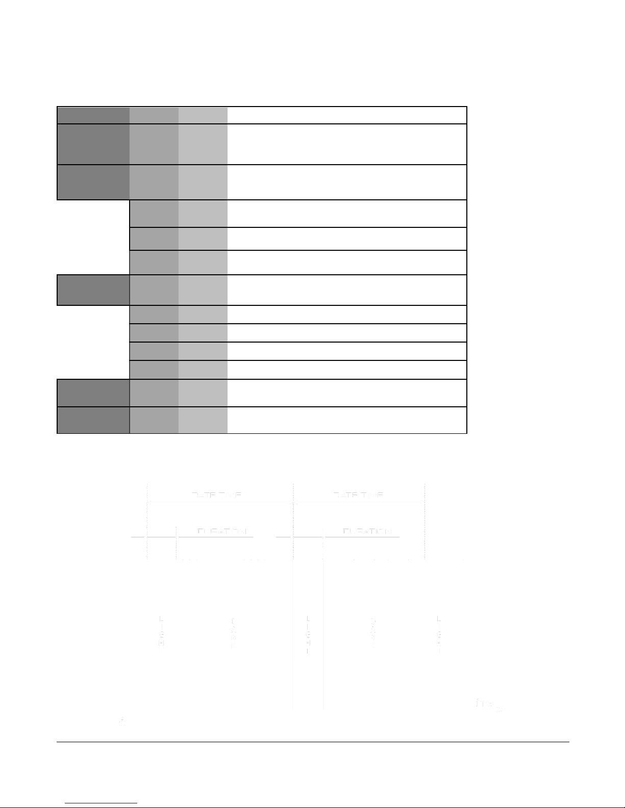
MENU MAP
Level 1
Level 2
Level 3
Notes
DMX
Address
1-512
Set the DMX start address
Control
In this menu function fixture control options can be
selected
DC
DMX mode is set to 1 channel (Intensity)
F3
DMX mode is set to 3 channels (Int+Dur+Rate)
F4
DMX mode is set to 4 channels
(Int+Dur+Rate+Eff)
Manual
Manual control of fixture effects. Stand-alone
function.
Int
0-255
Set strobe intensity
Dur
0-255
Set strobe duration
Rate
0-255
Set strobe rate
Eff
0-255
Set strobe effects
Measure
Displays system measurements (input voltage,
frequency, temperate, etc.)
Thermometer
Shows current temperature of device
DURATION TIME: RATE TIME RELATION.
SoLED W840 User Manual Version 4.1 051915 PRELIMILARY 10
FUNCTION DESCRIPTION
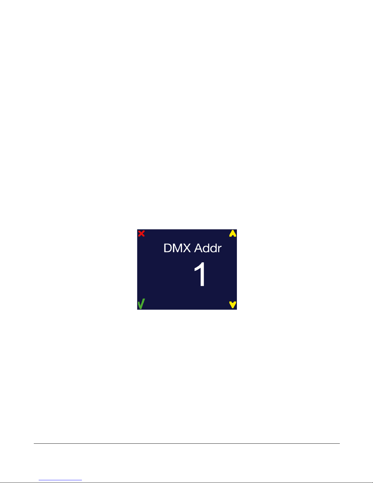
DMX ADDRESS
To set the required DMX Address, you must:
1) Press and hold <MENU> button to open the Main Menu.
2) Use <UP>and <DOWN> buttons to find the DMX Address submenu.
3) Press < > button to access the DMX Address value change submenu.
4) Use <UP> and <DOWN> buttons to set necessary DMX Address value (e.g. DMX Address 1).
5) Use < > button to confirm new DMX Address.
6) When the new DMX Address is confirmed return to Main Menu. Press < X > button to return fixture at
the work state.
7) At work state, control panel display shows current DMX Address, in this case 1.
Table des matières
Autres manuels Solaris Équipement d'éclairage


Manuels Équipement d'éclairage populaires d'autres marques


Qazqa
Qazqa Suplux SL 3 Black 103062 Manuel utilisateur

Commercial Electric
Commercial Electric 54568141 Manuel utilisateur

CREE LIGHTING
CREE LIGHTING 304 Series Manuel utilisateur

Goobay
Goobay 49867 Manuel utilisateur

ECOMAN ITALIA
ECOMAN ITALIA LED T8 Manuel utilisateur

Alkalite
Alkalite Krypton KT-81 Manuel utilisateur


