Solar MD SS4037-11 Manuel utilisateur
Solar MD (PTY) ltd.
Unit 23, Alternator Park
Montague Gardens 7441
Cape Town, South Africa
INSTALLATION MANUAL
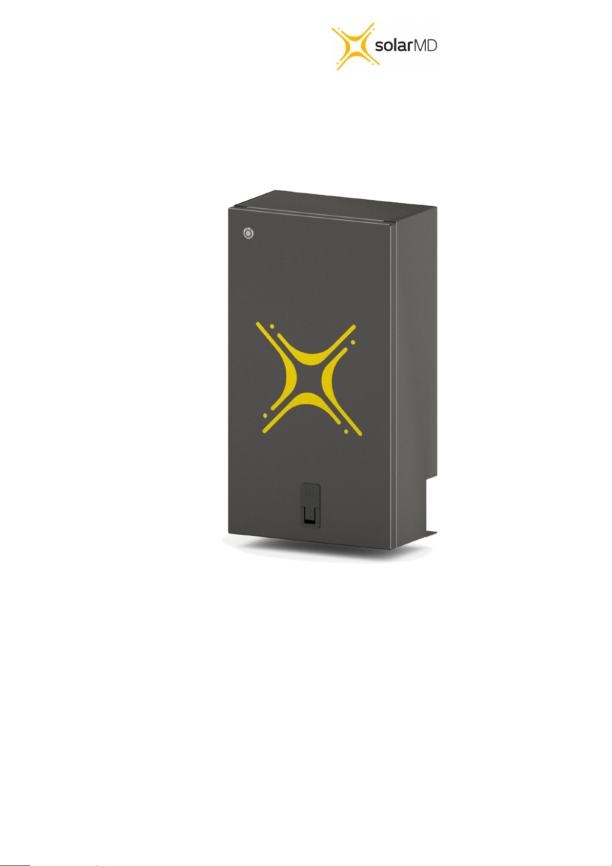
Advanced Lithium-Ion battery
SS4037-11

Unit 23, Alternator Park
Montague Gardens 7441
Cape Town, South Africa
Introduction 2
Product Description 2
Product Specifications 2
Errors or Inaccuracies 2
Copyrights 3
Safety Information 3
⚠ Warnings ⚠ Cautions 3
Specification 4
Mechanical installation 5
Installing bottom cover plate 6
Electrical installation 7
Commissioning 9
Multicolor multipurpose button 10
Button function 10
Button indication
BMS Warnings and Errors 12
CANBUS connection.
CANBUS warnings.
Troubleshooting Warnings / Errors
Maximum charging / discharging voltages for non supported
devices.
1
SS4037-11 INSTALLATION MANUAL v1.0
11
18
19
20
21

Unit 23, Alternator Park
Montague Gardens 7441
Cape Town, South Africa
Introduction
This manual is intended to provide assistance to an installer for the installation and
commissioning of the range of Solar MD Lithium Ion phosphate (LiFePO4) energy storage
solutions.
Product Description
meet most residential applications. The rated voltage is 51.2V nominal (to suit 48V systems).
WARNING: Read the entire document before installing or using the Solar MD battery. Failure
to comply with the instructions or warnings in this document could result in electrical shock or
serious injury that can result in death or damage to the product that can render the SS4037
Solar MD battery inoperable.
2
SS4037-11 INSTALLATION MANUAL v1.0
The SS4037-11 battery solution is available in one standard size and can be paralleled to
Larger systems are provided by Solar MD based on specific project requirements.

Unit 23, Alternator Park
Montague Gardens 7441
Cape Town, South Africa
Product Specifications
improvements at any time.
Errors or Inaccuracies
To communicate any inaccuracies, omissions or to provide general feedback regarding this
manual, send an email to [email protected]
Copyrights
All information in this document is subject to the copyright of Solar MD (Pty) Ltd. Additional
information is available upon request.
Safety Information
This manual contains important instructions and warnings that must be followed when using
⚠ Warnings ⚠ Cautions
● For communication and other information please read the BMS manual.
● Do not attempt to disassemble, repair, modify, or tamper with this battery unit.
● Do not insert foreign objects into any part of battery unit.
● Avoid exposure to any moisture.
● Do not expose to extreme temperatures.
● Do not drill any holes into the box.
● Use only an approved Solar MD installer to install this product.
3
SS4037-11 INSTALLATION MANUAL v1.0
All SS4037-11 specifications & descriptions contained in this document are verified to be
accurate at the time of printing. Solar MD reserves the right to make any product revisions &
SS4037-11.
Read all instructions before installing and using the SS4037-11.
Failure to comply will void the warranty
● Use SS4037-11 only as instructed.

Unit 23, Alternator Park
Montague Gardens 7441
Cape Town, South Africa
Specification
Battery type
Lithium Iron
Phosphate
Scalability
Yes
r Battery module
Communication
CANBUS 500kbps/CAN 2.0B
Rated battery capacity
3686 Wh
Can BUS termination
Single 120 Ohm
Output power
Max 5 kW / 100A
Canbus id range:
256 - 499
Usable battery energy @ 0.3\C
3.68 kWh
Protection method
Cell level: uv / ov / oc
Position: x / y / x
Acceleration: x / y / z
Temperature: ot / ut
Nominal voltage
51.2V
Protection phy
Mechanical relay NO
Number of battery modules
1 module
Com (CANBUS ) isolation
Yes 1.5kV
Weight
37kg
Transportation protection
Yes
Operating voltage
44.8V-55.6Vdc
Indicator
Led, programmable
Communication
CANBUS
Addition IO
3 GPO
Dimensions of SS44037: h/w/d
620mm/320mm
/200mm
Cell balancing
Passive balancing
Net Weight of SS4037
35 Kg
Counters
Cycle counters and SoH
Battery cycle life [+25 ‘C]
> 4000
AUX power output
5V 1A max
Charging efficiency
99%
Storage duration
6 months@+25℃
Operating temperature
-5℃ ~+50℃
Safety standards compliance
IEC 62619/UN 38.3/UL1642
Transport
UN3480 & UN38.3
Cell Certificate
TUV / CE / RCM / UL1642
4
SS4037-11
SS4037-11 INSTALLATION MANUAL v1.0
Solar MD 3.7kWh SS4037-11 specification
1.38C
Unit 23, Alternator Park
Montague Gardens 7441
Cape Town, South Africa
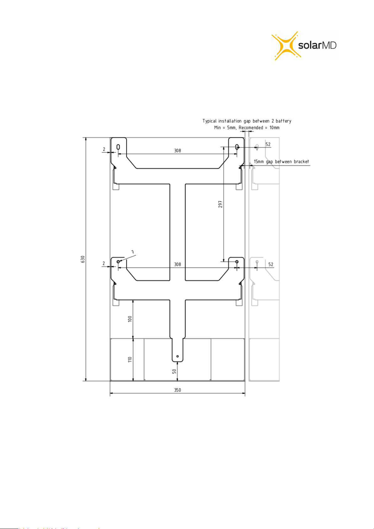
Mechanical installation
Figure 1: Rear Battery Bracket
Please use the correct mounting screws for the correct wall surface. Screw head should not
be bigger than 16mm in diameter. The Battery is only to be installed in the upright position
with a maximum tilt angle of 30 degrees.
5
SS4037-11 INSTALLATION MANUAL v1.0
Unit 23, Alternator Park
Montague Gardens 7441
Cape Town, South Africa
Figure 2: Maximum tilt angle
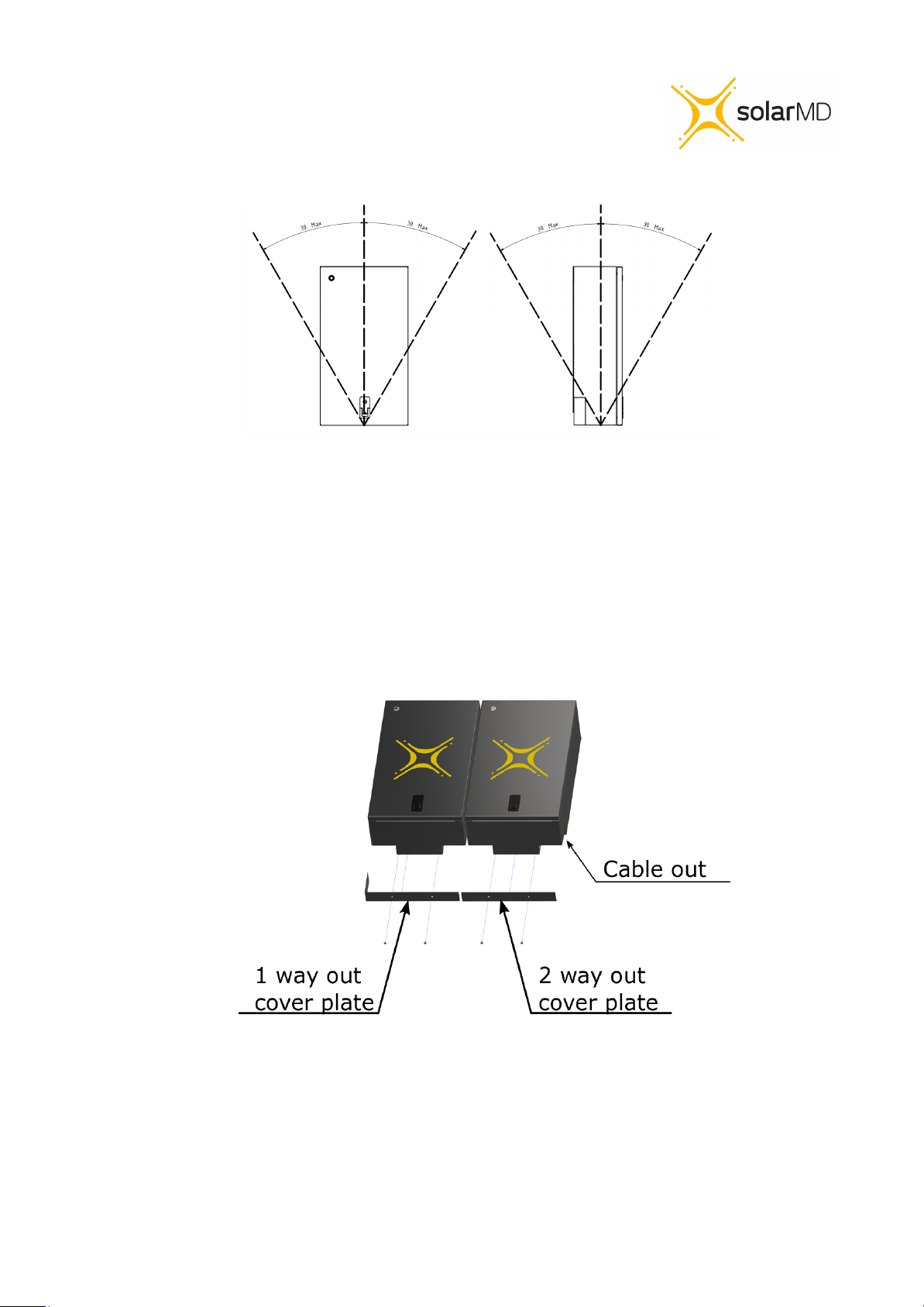
Installing bottom cover plate
Figure 3: Bottom cover installation for single or dual cable exit points
The Battery comes with two covers for single or dual cable exit points. Use the 1 or 2 way out cover
plate and fix it with the two M5x6 bolts provided in the box.
6
SS4037-11 INSTALLATION MANUAL v1.0
Unit 23, Alternator Park
Montague Gardens 7441
Cape Town, South Africa
Electrical installation
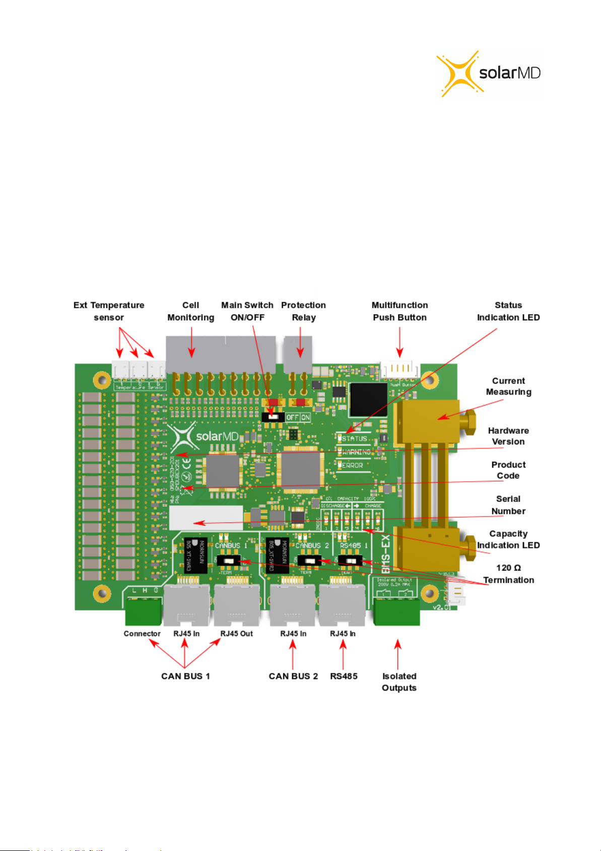
Step 1. Before connecting anything be sure that battery is off and the ON/OFF switch (fig4
pos 3) is in the OFF position.
Figure 4: BMS board component location
7
SS4037-11 INSTALLATION MANUAL v1.0
Unit 23, Alternator Park
Montague Gardens 7441
Cape Town, South Africa
Connecting Inverters/chargers/UPS to the battery unit while it is ON can cause big sparks
due to capacitors inside the connected device. This could cause serious injuries.
Connecting main battery terminal must be with the correct size cable.
Based on the rated current of the battery and inverter as well as cable length.
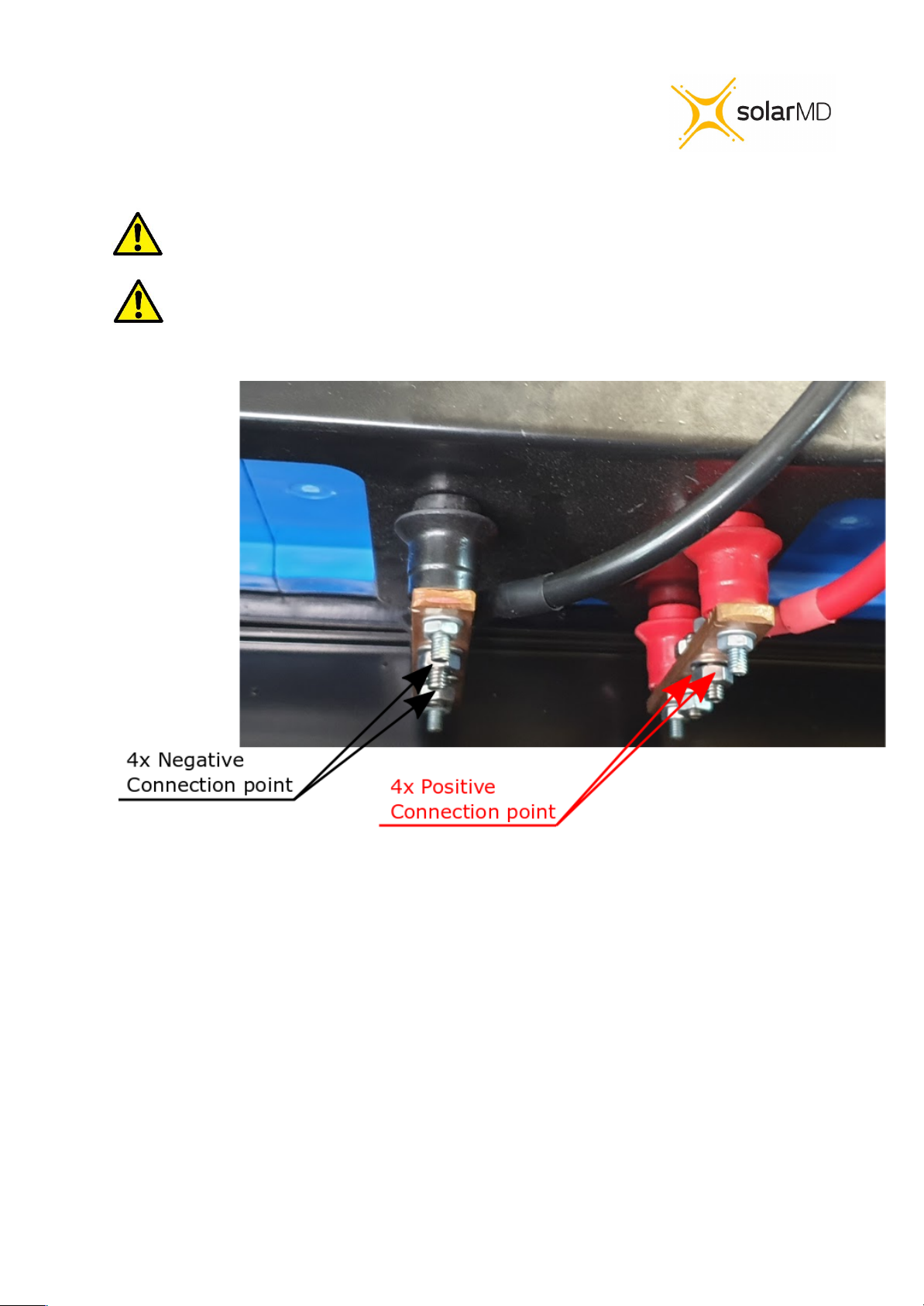
Figure 5 connection terminal
Step 2. Connect the negative cable to the battery negative busbar and positive to battery
positive as shown is figure 5 Make sure that all the connections are tight.
All used connection points should be a suitably tightened, ensuring good electrical
connection between the lug and busbar. A bad connection could cause serious damage to
the battery and inverter, and could void the warranty.
8
SS4037-11 INSTALLATION MANUAL v1.0
Unit 23, Alternator Park
Montague Gardens 7441
Cape Town, South Africa
Commissioning
Step 1. Ensure all DC cables are tight according to specifications.
Step 2. If the battery operates in parallel with other Energy sources, make sure that the
difference between battery voltage and DC bus is not more than 2.5V. If greater than 2.5V
please Charge or Discharge other source accordingly until voltage difference is in safe
ranges under 2.5V.
Caution! A hot connection with difference in voltage can cause very high
equalization current which can burn the fuses of the battery!
Caution! Measure the voltage of the battery before connecting the dc
Cables.
Step 3. Turn BMS board ON/OFF switch to the ON position (figure 4 pos 3)
Step 4. Connect Multi-purpose button if not connected to the BMS board connector see
(figure 4 pos 5)
Step 5. Hold multi-purpose button until light come on.
Note: If commissioning two or more batteries.
Once the system is switched on and load is added, measure current flow on
each battery. Ensure that the load is distributed across each battery equally.
Warning! If the battery does not switch the main protection Contact ON in 7
seconds, please check BMS board indication LED for faults. See section BMS
9
Error and Warnings on page 12 of this manual.
SS4037-11 INSTALLATION MANUAL v1.0
Ce manuel convient aux modèles suivants
1
Table des matières
Manuels Bloc de piles populaires d'autres marques


IOGear
IOGear GBP24V Series Manuel utilisateur

Inventus Power
Inventus Power PROTRXion S-12V100-TRX-HD Manuel utilisateur

Clas Ohlson
Clas Ohlson PW-290A Manuel utilisateur

EINHELL
EINHELL MULTI-Ah Power X-Change Plus Manuel utilisateur

Samsung
Samsung EB-U3300 Manuel utilisateur

ECTIVE
ECTIVE LC Series Manuel utilisateur