Sol GreenWay GRNWY-50 Instructions d'installation
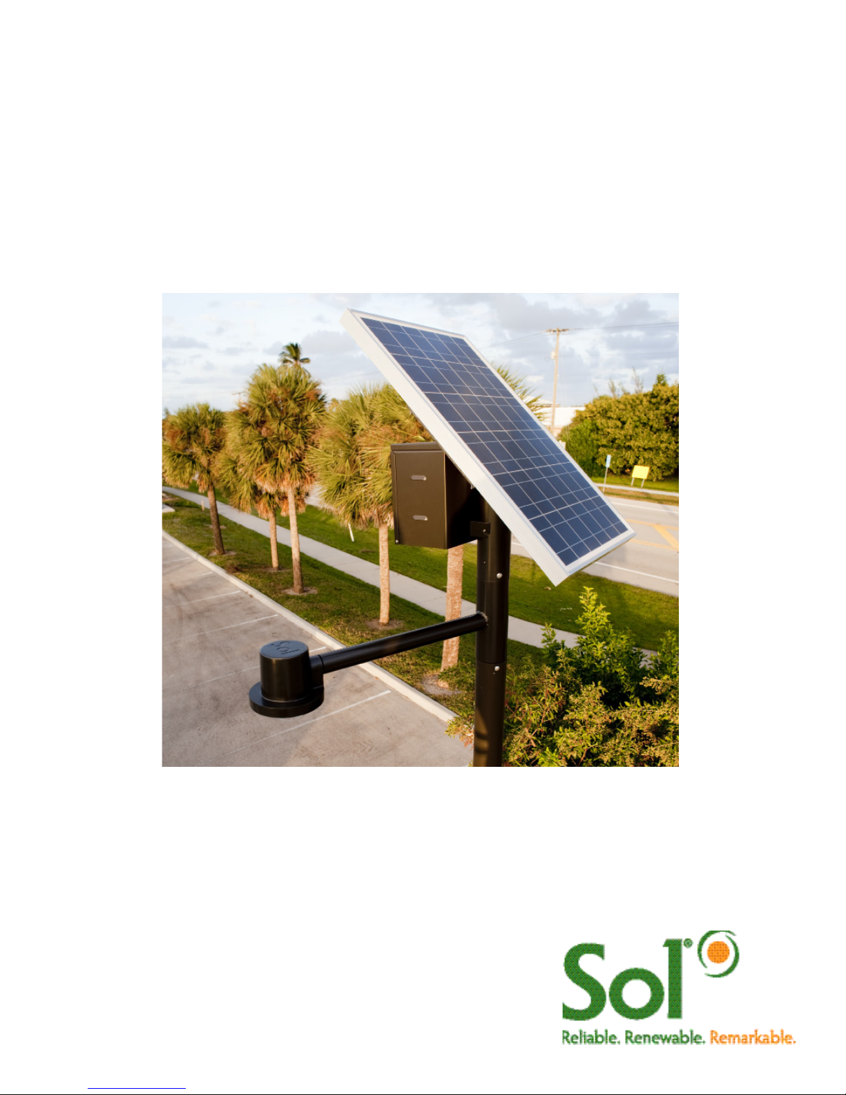
GreenWay™
Solar LED Path and Trail Lighting System
Installation and
Owner’s Manual

2 GreenWay™ installation & operation manual 0410 MKTG-IM-GREEN-002
IMPORTANT SAFETY INSTRUCTIONS - SAVE THESE INSTRUCTIONS
This manual contains important instructions for the SOL GreenWay™ Series that shall
be followed during installation and maintenance of the charge controller.
The SOL GreenWay™ is a patented, off-grid, standalone, solar-powered lighting system. Years of
engineering, development, and testing ensure that this system meets or exceeds all performance and
reliability specifications. Every system that leaves our factory has been quality control tested and inspected to
assure you of an easy installation and highly dependable performance. All mechanical fittings and electrical
connections are designed for simple and reliable installation. The system is ready for use immediately after
the components are mounted and the plug and play connectors are joined.
IMPORTANT NOTES AND WARNINGS
This installation and instruction manual provides installation, operation, and maintenance instructions for
the SOL GreenWay™ solar LED lighting system. The entire contents of this manual should be thoroughly
reviewed and understood prior to installing this equipment. Do not discard this manual. It contains complete
maintenance instructions, a troubleshooting chart, and a spare parts list. To insure proper operation of this
equipment, it is important that the equipment be utilized for its intended use. Any use of this equipment for
purposes other than those intended will void all warranties.
Installation and/or troubleshooting should be performed only by qualified personnel. Follow local
codes at all times during installation of the GreenWay™.
Be very careful when working with batteries.
Do not allow bare ends of the wires to touch each other or grounded metal parts while connected
to the controller. This will damage the controller.
CONTENTS
Section 1 Site Selection and System Overview 3
Section 2 Parts List 4
Section 3 Pole Preparation and Attaching PV Array 5
Section 4 Assembling Components and Riveting Arm Assembly 6
Section 5 Mounting Battery Box and Installing Battery 7
Section 6 Installing Luminaire and System Wiring 7-8
Section 7 Controller 9-11
Section 8 Operation, Maintenance and Troubleshooting 12-15
Section 9 Warranty 16
Operational Principles
The SOL GreenWay™ solar LED lighting system is designed to provide reliable operation and illumination
all year. The solar array (the photovoltaic panel, or PV panels) re-charges the battery each day, replacing
energy that was used during the previous evening so that illumination can again be provided during the
following evening. The system is designed with a reserve, so that regular illumination will continue to be
provided during periods of rainy or cloudy weather. The controller monitors battery condition and will shut off
illumination if the battery charge drops below a specified level. This may occur if there is a prolonged rainy or
cloudy weather or if the solar array is shaded during part of the day. The controller automatically restarts the
system when the condition is corrected and the battery charge returns to the specified level, protecting the
batteries.
3 GreenWay™ installation & operation manual 0410 MKTG-IM-GREEN-002
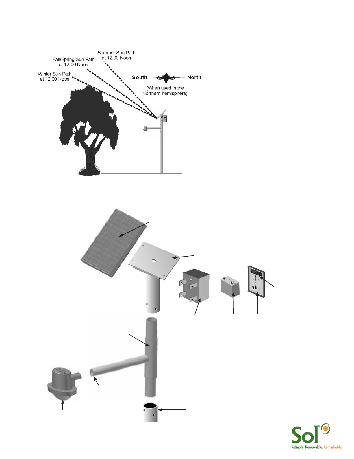
Site Selection and Preparation
Locate and install the PV panels in an area where the PV panels can face the equator (due south in the
Northern hemisphere) and not shaded by trees, poles, buildings, or other objects during the day (Figure 1).
Do not locate in an area where there is
excessive ambient or reflected light at night
which may simulate daylight and cause the
system controller to turn off the system.
Installing in a location where the solar
panels are shaded during part of the day will
prevent the solar panel from fully charging
the battery, reducing the hours of nighttime
illumination and possibly damaging the
battery. If installed near a tree, check the
tree branches every three months and trim
when needed.
Installation of the solar light system and
pole must comply structural engineering
requirements for local and national codes.
FIGURE 1 LOCATING AND POSITIONING THE PV PANELS
System Overview
Pole
PV Assembly
PV Modules- Always facing EQUATOR (South in
Northern Hemisphere)
LED Luminaire
Battery Enclosure (B.E.)
Arm Assembly
FIGURE 2 SYSTEM OVERVIEW
Holes for Luminaire install
must face DOWN
Battery Battery Box
Cover
Controller
4 GreenWay™ installation & operation manual 0410 MKTG-IM-GREEN-002
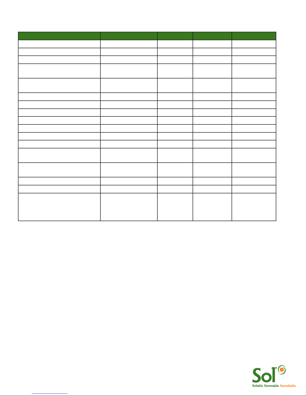
DESCRIPTION PART NUMBER GRNWY-50 GRNWY-80 GRNWY-125
Pole 302012-007DB 1 1 1
Solar Panel Assembly 30040-001 1
Solar Panel Assembly 30080-003 1
Solar Panel Assembly 33172-010 1
Solar Panel Mount 15 Deg
or 45 Degrees
302012-101*
302012-103*
1
1
1
Arm Assembly 302012-201 1 1 1
Battery 86008-001 1 1 1
Battery Box 202721-200 1 1 1
Solar Panel Harness 855200-031 1 1 1
Battery Harness 855200-002 1 1 1
LED Harness 805000-004 1 1 1
aiSUN™ Controller 855101-200 1 1 1
aiSUN™ 56L Single Battery
Harness
855200-010
Solar Panel Assembly Mounting
Hardware
GWHP-PV 4 4 4
Battery Box Mounting Hardware GWHP-BB 4 4 4
Drive Rivets DR375X.50GR 11 11 11
Fixture Assembly:
Ascot
Shoebox (1Q)
781001-100
781001-200
1 1 1
Parts List
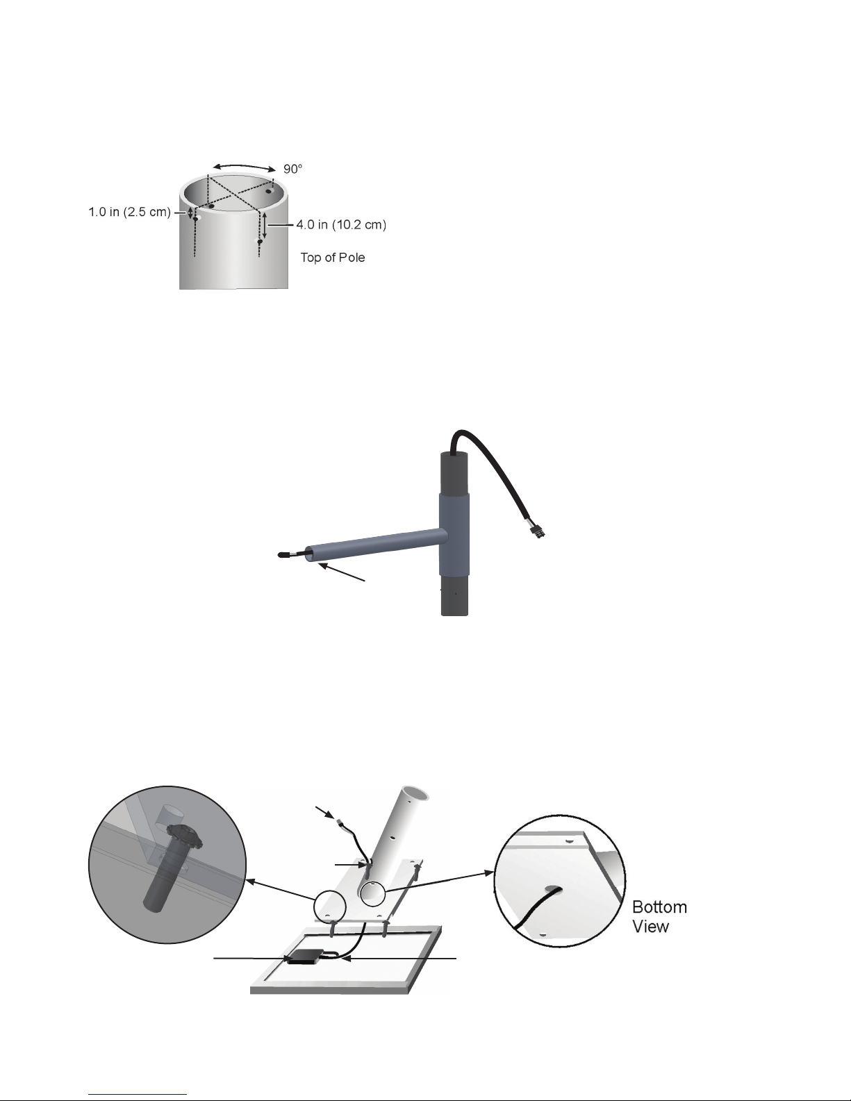
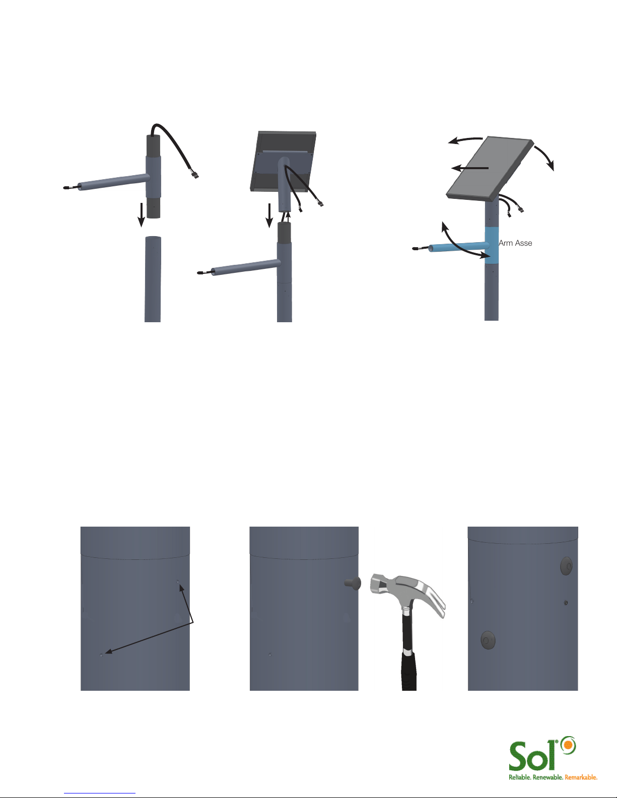
Pole Preparation and Installation
Four holes must be drilled at the top of the pole. This should be done before the pole is set and anchored.
Drill two equally-spaced 0.125-inch (3.2 mm) pilot holes 1 inch (2.5 cm) below the top of the pole, as shown
in Figure 3. Drill two additional equally-spaced 0.125-inch (3.2 mm) pilot holes 4 inches (10.2 cm) below the
top of the pole, as shown in Figure 3. Position the holes 90 degrees from the holes drilled in previous step.
FIGURE 3 DRILLING 4 HOLES AT TOP OF POLE
FIGURE 4 ROUTING LUMINAIRE LOAD CABLE
Routing Luminaire Load Cable Through Arm Assembly
Insert the male end of the luminaire load cable (with cord grip in plastic bag) into the fixture end of the arm. Slide the
luminaire load cable through the arm assembly until the connector plug emerges from pipe end of the arm assembly,
opposite side of luminaire install holes (Figure 4).
FIGURE 5 ATTACHING PV ASSEMBLY TO PV MODULE
Attaching the PV Module to the PV Mount
Lay the PV module upside down on a protected surface (cardboard shipping carton can be used) and
position the PV mount over the PV module so that the hole and grommet on the side of the pipe face the
PV module junction box. Route the PV cable in through the center hole and out through the side of the PV
mount. Fasten the PV mount to the PV module using the 4x bolts and washers provided (Figure 5).
Pole Anchoring
It is imperative that the pole is properly anchored.
Standard pole anchoring methods may be used,
providing they meet the engineering requirements
for EPA and weight of the system you have
purchased.
Holes for Luminaire install
must face DOWN
Junction Box
Hole & Grommet
MC Connectors
to PV Module
PV Module Cable
6 GreenWay™ installation & operation manual 0410 MKTG-IM-GREEN-002
Arm Assembly
Assembling the Components
After the pole has been set and anchored, slide the arm assembly into the top of the pole (Figure 6a). Route the PV
load cable through bottom of the solar panel assembly pipe and out through the grommet and hole on the front of the
pipe (Figure 6b). Place the solar panel assembly on the top of the arm assembly. Swing the arm assembly so that the
light fixture (which will be attached to the end of the arm) is in the desired position (Figure 6c)
FIGURE 6 ASSEMBLING ARM ASSEMBLY AND PV ASSEMBLY TO POLE
Arm Assembly
Pole
Luminaire Load
Cable
Luminaire Load
Cable
PV Module Cable
Equator (Due South in
Northern Hemisphere)
PV Assembly
abc
Riveting the Arm Assembly to the Pole and Solar Panel Assembly to the Arm Assembly
Verify that the arm is positioned so that the light fixture (which will be attached to the end of the arm) is in the desired
orientation. Using one of the pilot holes at the upper end of the pole as a guide, drill one rivet hole using a U.S. “W”
gauge (0.386-inch) drill bit (or use a 25/64-inch drill bit if “W” gauge not available). Drill through the pilot hole and then
through the arm assembly stock beneath the pilot hole (drill & rivet one pilot hole at a time). Place a drive rivet in the rivet
hole (Figure 7a). Pound the drive rivet into the hole (Figure 7b) until the head of the drive rivet is tight against the side of
the pole (Figure 17c). Install the three remaining drive rivets in the arm assembly.
Verify that the solar panel is positioned so that the solar panel is facing due south. Using one of the pilot holes at the
lower end of the solar panel assembly as a guide, drill one rivet hole using a U.S. “W” gauge (0.386-inch) drill bit. Drill
and rivot one pilot hole at a time following same instructions used for the arm assembly.
FIGURE 7 RIVETING THE ARM ASSEMBLY AND SOLAR PANEL ASSEMBLY
b c
Drill holes
in pilot
holes
(4 places)
a
7 GreenWay™ installation & operation manual 0410 MKTG-IM-GREEN-002
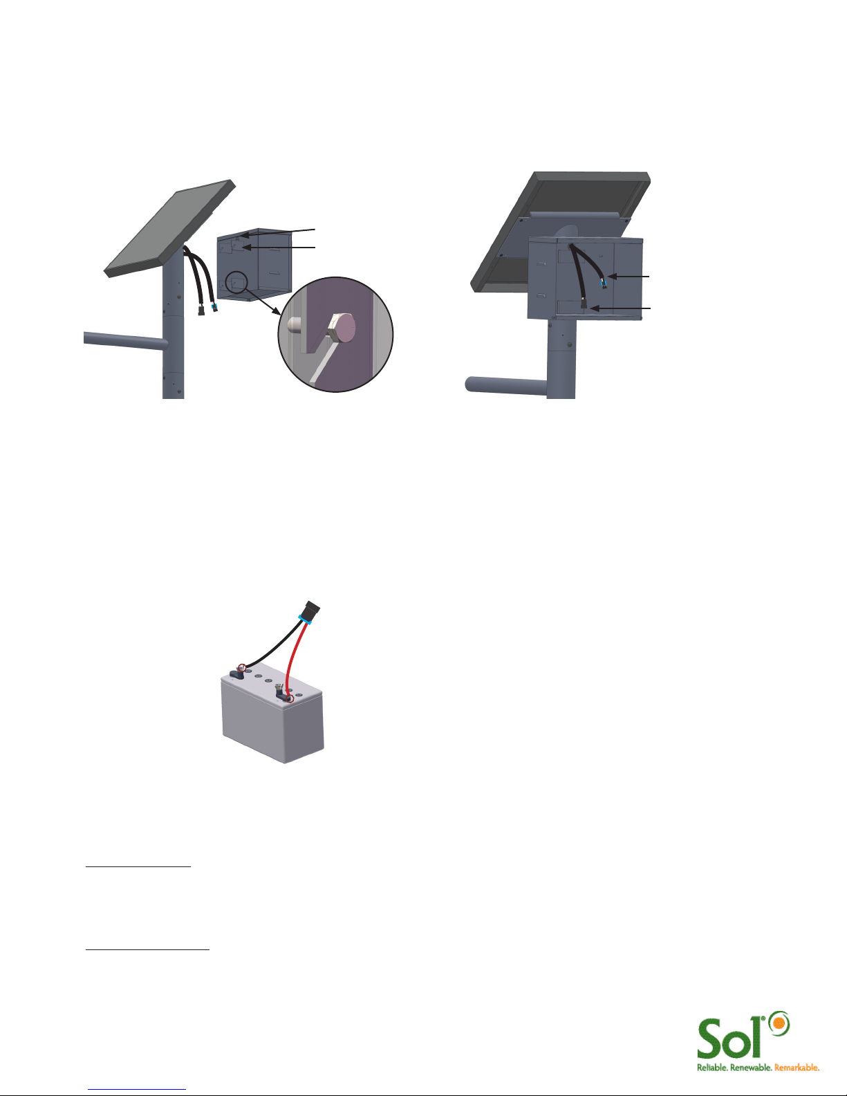
Mounting Battery Enclosure and Routing PV and Luminaire Cables
Route the ends of the solar PV cable and the Luminaire cable through the hole and grommet at the back of the battery
box, as shown in Figure 9. Loosely fasten the brackets at the back of the battery box to the pipe of the solar panel
mounting, using four 1/4”–20 x 1/2” hex head bolts. Securely tighten each bolt. Position the cables so they extend
inside the battery box at least 12 inches (30.5 cm).
FIGURE 9 MOUNTING BATTERY BOX FIGURE 10 ROUTING CABLES
PV Cable from PV Array
Luminaire cable from LED
Luminaire
Hole and Grommet
Bracket
Installing the Battery/Batteries
Loosely connect the battery harness to the battery terminals. When connecting the battery, connect the
positive terminal first (Red +). Protect the free (unconnected) ends of the battery harness from touching other
metal parts so they will not accidentally cause a short. Tighten the connection on both terminals. Place the
battery in the battery box. Connect the battery harness to the single aiSUN™ harness as shown in Figure 11.
Battery Harness - one for each battery
Black (-)Red (+)
Gel Cell 100 Ah
NRGLife™ Battery
FIGURE 11 BATTERY AND BATTERY HARNESS
Installing Luminaire
For Ascot Fixture:
Connect the connector from the LED luminaire to the connector at the end of the luminiare load cable.
Slide the LED fixture onto the arm. Adjust the LED fixture for the desired tilt. Secure the LED fixture to the arm using the
socket head bolts (Figure 12).
For Shoebox Fixture:
Loosen the set screws that secure the slip fitter. Plug LED luminaire connectors together. Slip fixture over pipe (guide
excess wires into pole). Secure set screws. To adjust angle remove circular cover using Phillips screwdriver. Using a
socket wrench, loosen bolt to adjust angle to desired angle. Tighten bolt and replace cover (Figure 13).

8 GreenWay™ installation & operation manual 0410 MKTG-IM-GREEN-002
System Wiring Diagram
All solar light systems with aiSUN™ controllers ship with Clik™ together wiring harnesses. This
eliminates field wiring and splicing. Use the wiring diagrams below for connecting your solar light
system. Note: includes a field replaceable fuse.
FIGURE 14 WIRING DIAGRAM
Battery 1
Black (-) (+) Red
Battery Harness
aiSUN™ Controller
PV Module
LED Luminaire
Brown (+)
Blue (-)
Luminaire Load
Cable
Black (-) Red (+)
Green-
Ground
aiSUN™ Single Harness
Black (+)
Orange (-)
This lamp (LED) is in excess of the Exempt Risk Group defined in IEC 62471:2006-07. This lamp (LED) has been found to be in the Risk
Group 2 classification at an exposure distance of 20 cm or less from the glass surface of the lamp. Care should be taken to avoid exposure
when operating and installing this lamp.
FIGURE 13 MOUNTING SHOEBOX
Set screws
FIGURE 12 MOUNTING ASCOT

9 GreenWay™ installation & operation manual 0410 MKTG-IM-GREEN-002
aiSUN™ Solar Light CPU
This guide describes how to complete the assembly of your light system when it is outfitted with an aiSUN™
CPU. aiSUN™ features & troubleshooting information is provided.
What does the aiSUN™ CPU do?
aiSUN™ is a unique solar charging controller and LED luminaire controller packaged into one intelligent solar
light CPU. aiSUN™ performs the following 2 tasks:
1. Charges batteries: Electricity generated by the PV module is modulated and controlled by the aiSUN™
to properly and safely charge the solar light’s NRGLife™ batteries.
2. Operates the LED Luminaire: Using a factory-installed configuration, aiSUN™ turns on the LED luminaire
after sunset and turns off the luminaire before sunrise as configured per each location. This includes
dimming and response to motion detection in some configurations.
aiSUN™ is factory configured for your location. No adjustments are required. Lights are programmed to run
in one several operating modes.
Operating mode is shown on the unit label as: HH.LLL.LLL.HH.LLL
(1) (2) (3)
(1) light setting after sunset
(2) light setting in the middle of the night
(3) light setting before sunrise
where: HH is the number of hours at full intensity and LLL is the light intensity in percentage
Dusk to Dawn unit label reads:
DD.100.000.00.000
Programmed Run unit label reads:
06.100.000.00.000
Split Night w/ Dimming (4 hours
at full, dim to 50%, 2 hours at full)
unit label reads:
04.100.050.02.100
Split Night (4 hours at full, turn off,
2 hours at full) code:
04.100.000.02.100
10 GreenWay™ installation & operation manual 0410 MKTG-IM-GREEN-002
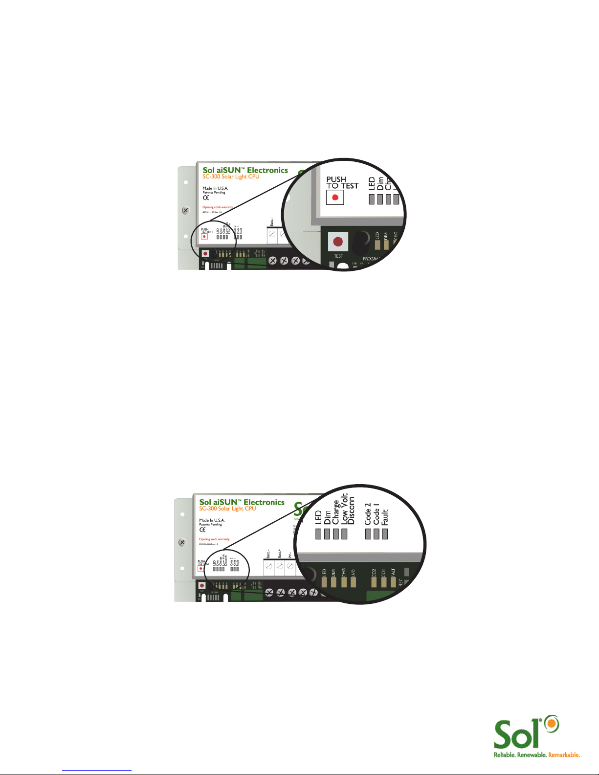
Solar Light System Test
Once all of the wires have been clicked together and the batteries are installed, perform a diagnostic test.
Press the “PUSH TO TEST” Button. This will indicate to the CPU to turn on the LED Luminaire(s) and
operate the lights at full intensity for 5 minutes. Several diagnostic LEDs will turn on & remain on for several
seconds. This is normal.
FIGURE 15 aiSUN™ SYSTEM TEST
Troubleshooting and Diagnostic LEDs
If the LED Luminaire turns on to full brightness, system operates OK and will automatically turn on & off with
sunset and sunrise.
If the LED Luminaire does not turn on as described, follow the Diagnostic LED table (below) to troubleshoot
the system.
If LED Luminaire does not turn on AND no Diagnostic LEDs are on, aiSUN™ is not powered, check battery
and fuse connections.
FIGURE 16 aiSUN™ TROUBLESHOOTING
Ce manuel convient aux modèles suivants
2
Table des matières
Autres manuels Sol Onduleur


