ϱ
&ŝŐƵƌĞϰ
Installation instructions:
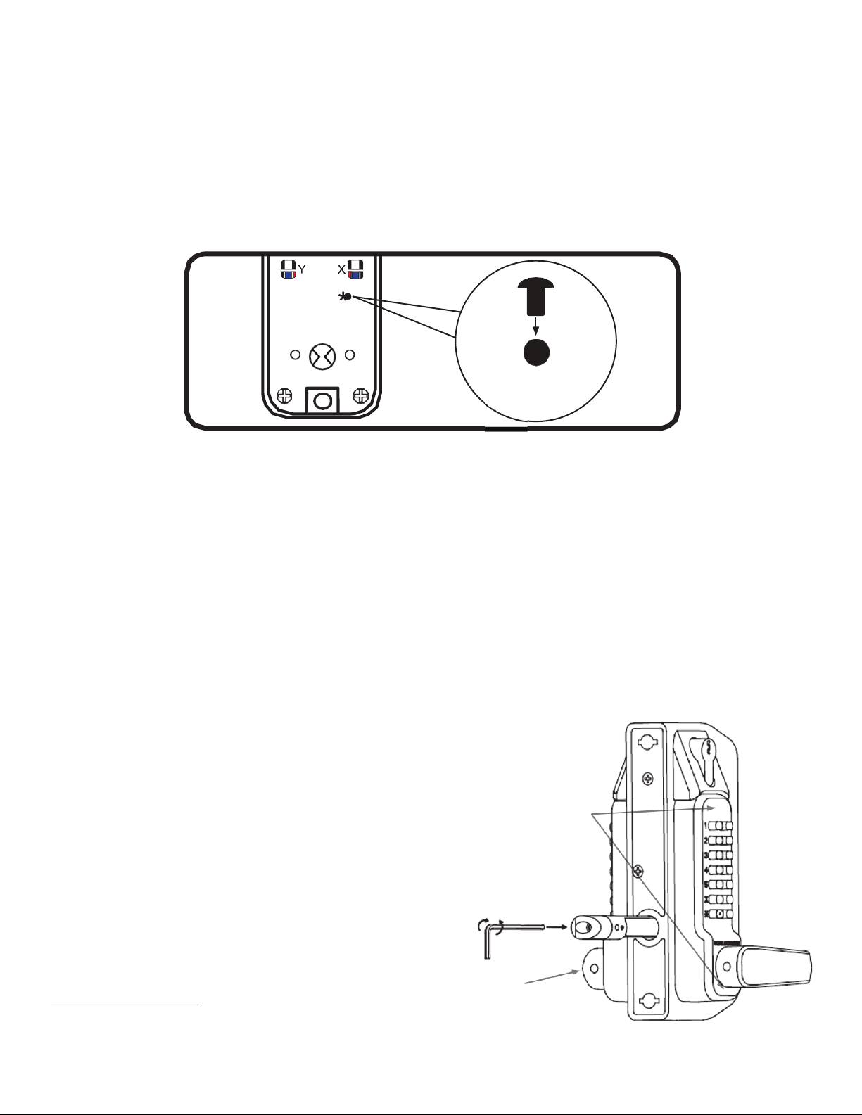
1.Establish the handing required for your lock installation and change if necessary following the
instructions above in “How to Change the Handing of your Lock”.
2.Enter the code and test the lock several times to ensure proper operation before proceeding.
3.Establish the position of the lock body on the gate frame/stile and using the provided drilling template,
mark the centers of both the 35/64”(14mm) holes and 51/64”(20mm) hole. Please note there is both an outside
and inside drilling template.
4.Drill the holes using the appropriate bits. Keep in mind that the 51/64”(20mm) goes all the way through
but the 35/64”(14mm) hole is for
the outside of the frame/stile only.
The hole on the inside of the
frame/stile is to be 11/32”(8.5mm).
The difference allows the head of
the “Socket Machine Screw” to
pass through the outside and
catch the inside wall of the gate
frame/stile.
5.Install the “Latch Bolt Finishing
Insert” into the outside
51/64”(20mm) hole and ensure it is
snugly and properly placed. You
should hear it snap into place.
6.Guide the latch projection of the
lock through the 51/64”(20mm)
hole from the inside of the gate
frame.
7.Using the “Socket Machine Screws
(item 2) and the “Spacers” (item 3), bolt the lock body to the gate stile. Make them snug but do not
tighten yet. The spacers are necessary to keep the socket machine screws from interfering with the
internal working of the lock.
8.Test the operation of the lock several times before proceeding here as well. It may be necessary to
loosen the “Socket Machine Screws” and slightly adjust the position of the lock to achieve the best
operation.
9.Once satisfied, tighten the “Socket Machine Screws” and secure the lock in its final position on the gate.
10.Now that you know where the lock will sit you can turn your attention to the “Gate Jamb Striker”. The
striker is complete with a gate stop to stop the gate in its travel and ensure the latch bolt catches
consistently.
11.Hold the “Gate Jamb Striker” on the latch post with center of the latch bolt receiver slot near the latch
bolt projection from the lock. Centering the latch bolt vertically in the slot will allow for some movement
up or down should the need arise.
12.Once you have determined its proper position you can mark and drill the two (2) 35/64”(14mm) holes to
mount it.
13.Once the holes are drilled push the supplied “Nutserts” into the holes. Place the “Gate Jamb Striker”
over top aligning the square holes and ensuring the gate stop is positioned appropriately for your gate
thickness.
14.Install the machine screws though the “Gate Jamb Striker” and thread by hand into the “Nutserts”
previously placed in the post.
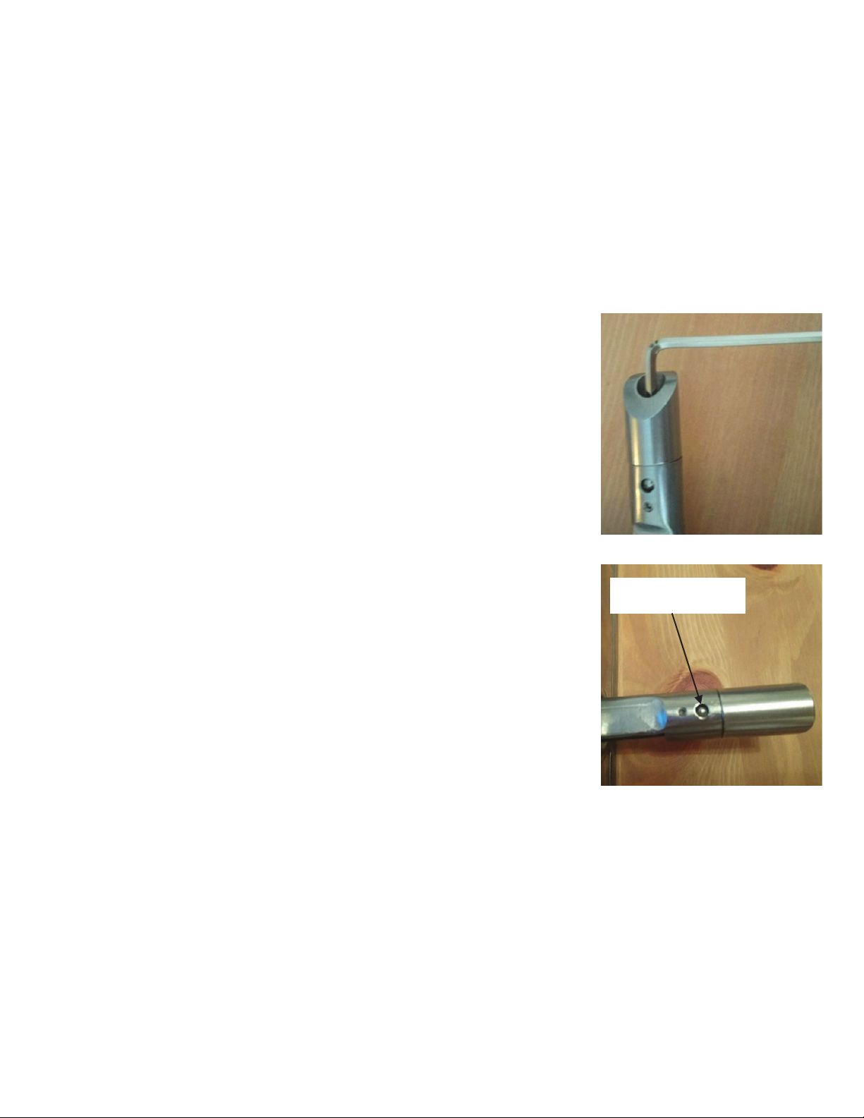
15.Tighten the Allen Screws with a 5mm Allen Wrench until tight.