Smith FS300 Manuel utilisateur

FS300 Gas
Heavy duty remover
User Manual
(954) 941-9744
www.SMITHMFG.com
MANUFACTURING
Cutters / Removers / Parts / Support
1-800-653-9311
www.SmithMfg.com
Phone: 954-941-9744 • Fax: 954-545-0348

SMITH Manufacturing 1-954-941-9744 www.SmithMfg.com
FS300
VERSION 8/2013
Gas
SMITH Manufacturing 1-954-941-9744 www.SmithMfg.com
INTRODUCTION
2
Congratulations on purchasing the
FS300™ heavy duty remover from
SMITH Mfg. Company.
Your machine will:
• Clean surfaces impacted by grease, oil,
plastics, tars, resins, tile adhesives, ice and
more
• Plane or mill asphalt and concrete surfaces
• Remove high spots in curbs and gutters
• Eliminate trip-hazards on concrete sidewalks
• Mill areas for rumble strips
• Clean out cracks and joints
• Create anti-slip patterns in walkways and barns
• Prepare surfaces for new coating applications
• Permanently remove all road and surface
coatings to include:
epoxy, urethane, thermoplastic, paint,
glue-backed tapes and more...
• Groove-inlay asphalt for striping
BEFORE START-UP,
READ THIS..
Please read all operating instructions, including
the provided motor manual and be completely
familiar with your equipment before operating.
When in doubt, please contact SMITH
Manufacturing Customer Service for operational
details. This Owner’s Manual will guide you
through the removal process, from start to nish,
and show you how to care for your machine.
Page Contents
2Index / Introduction
3Safety Guidelines
4Your FS300 Surface Preparator
5Handle Adjustment Instructions
6Machine Start-Up
7Substrate Removal
8Storage, Ordering, and Warranty Claims
9Troubleshooting
10 Maintenance Check List
11-12 General maintenance
13-14 Bearing replacement
15-17 Optional Equipment
18-19 Maintenance Log
20 Limited Equipment Warranty
21 Warranty Activation
INDEX

SMITH Manufacturing 1-954-941-9744 www.SmithMfg.com
VERSION 8/2013
FS300
Gas
3
UNCRATING EQUIPMENT
When you uncrate your equipment, make certain
that the machine has not been damaged and
that all fasteners and guards are properly
tightened.
Your machine may not have been shipped
assembled with cutters and other accessories.
Assembly may be required.
REMEMBER: Only authorized, experienced and
properly trained personnel should operate this
equipment. Operating personnel should prac-
tice safety at all times and ear protective gear
(gloves, goggles, safety vests, ear plugs, steel-
toe shoes, etc.)
• Always wear protective equipment, including
ear protection and goggles.
• Never wear baggy or loose tting clothing that
can be caught on controls or moving parts.
• The surface preparator can emit ying
particles and debris during operation. Never
operate the machine near bystanders, animals
or children.
• Check uid levels and get acquainted with the
controls.
• Do not operate the machine in an explosive
atmosphere, near combustible materials, or
when gas fumes may not be properly dispersed.
• Never leave the machine unattended when
running, and you must hold onto the handle with
two hands when the cutter drum is engaged.
• Ensure that all guards are in place before the
machine is operated, since rotating and moving
parts will cause injury upon contact.
• Make sure that the machine is unplugged from
any power source before servicing.
Incorrect use of the surface planer can
result in property damage, personal injury,
or death. Be sure to read and follow all
directions and precautions as outlined in
this manual.
SAFETY GUIDELINES

SMITH Manufacturing 1-954-941-9744 www.SmithMfg.com
FS300
VERSION 8/2013
Gas
SMITH Manufacturing 1-954-941-9744 www.SmithMfg.com
YOUR FS300TM SURFACE PREPARATOR
Please take time to familiarize yourself with the FS300™’s
controls, as well as some of the features of your new machine.
Read the engine manual before preparing the engine for starting.
Adjustable Handlebar
Cutter height adjustment
Corded “engine kill” button
Removable Side Plate
4
Oil Dipstick
Engine Shut-Off
Gas Tank
Throttle
Cyclone Air Cleaner

SMITH Manufacturing 1-954-941-9744 www.SmithMfg.com
VERSION 8/2013
FS300
Gas
HANDLE BAR ADJUSTMENT
The handlebars are equipped with a high-density
vibration suppression material to minimize
operator fatigue and increase comfort level when
operating equipment. To adjust the handlebars
to a new position for different height operators
please follow these steps:
• Using a wrench or socket (13mm), loosen
the bolts on both sides of the handlebars
two to three turns only.
• Adjust handlebar to desired position and
re-tighten the 4 screws
Never operate with handlebars loose.
The bolts must be fastened tightly assuring
the handle is locked into position.
Loosen to
adjust
5

SMITH Manufacturing 1-954-941-9744 www.SmithMfg.com
FS300
VERSION 8/2013
Gas
SMITH Manufacturing 1-954-941-9744 www.SmithMfg.com
MACHINE START-UP
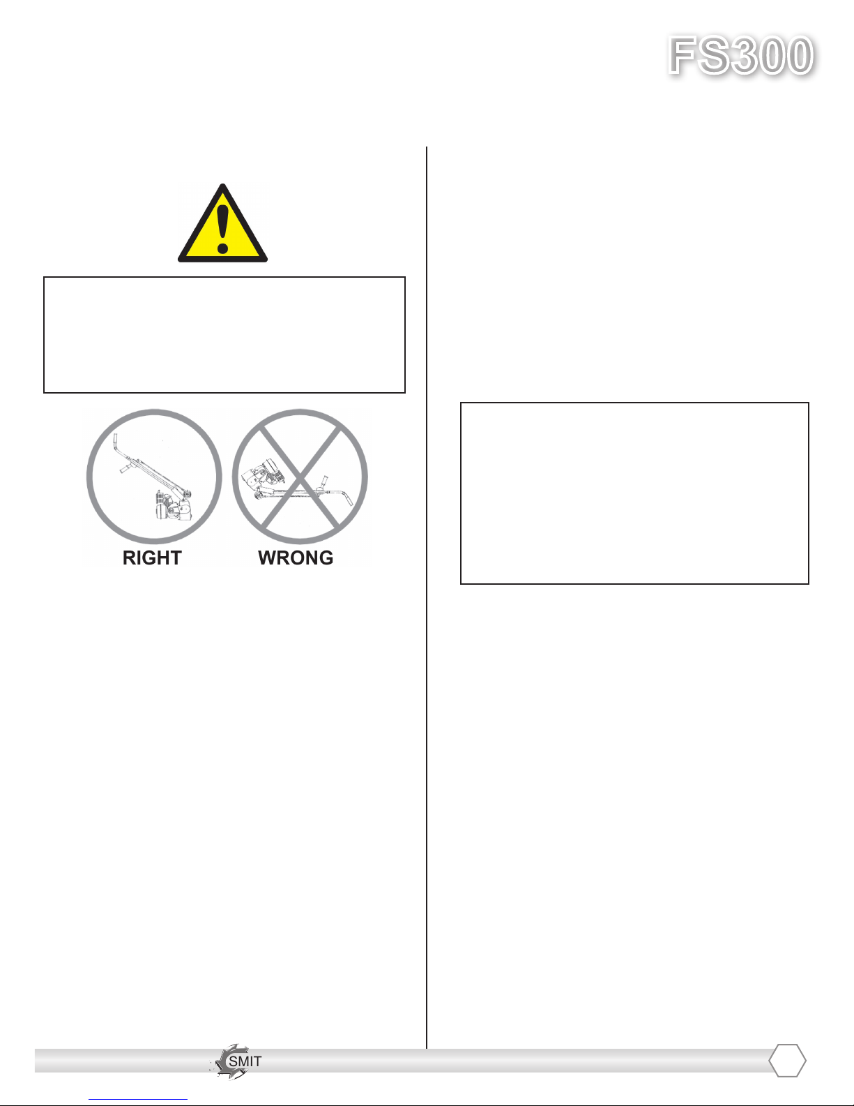
Do not start machine while drum is in
contact with the ground. Doing so can
cause the operator to lose control of the
machine, resulting in property damage
and/or personal injury.
NOTE: Do not attempt to raise or lower the cam
lever by force. If it does not move effortlessly,
raise or lower the hand wheel until the cam lever
can be adjusted. Open the fuel cock on the
carburator and then place the throttle lever at the
“Fast Idle” position. Start the engine, open choke
slightly to prevent ooding. Move throttle control
to open or run position when engine is warmed
up. Increase throttle to maximum operating posi-
tion (approx. 2800RPM) and close choke. Before
substrate removal, test run the drum with cutters
not touching the surface. If there is excessive vi-
bration, you need to re-balance the cutter set-up,
check bearing condition, and/or make sure that
the drive shaft is secured.
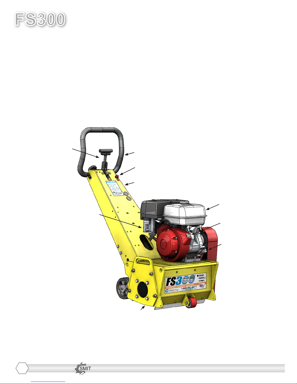
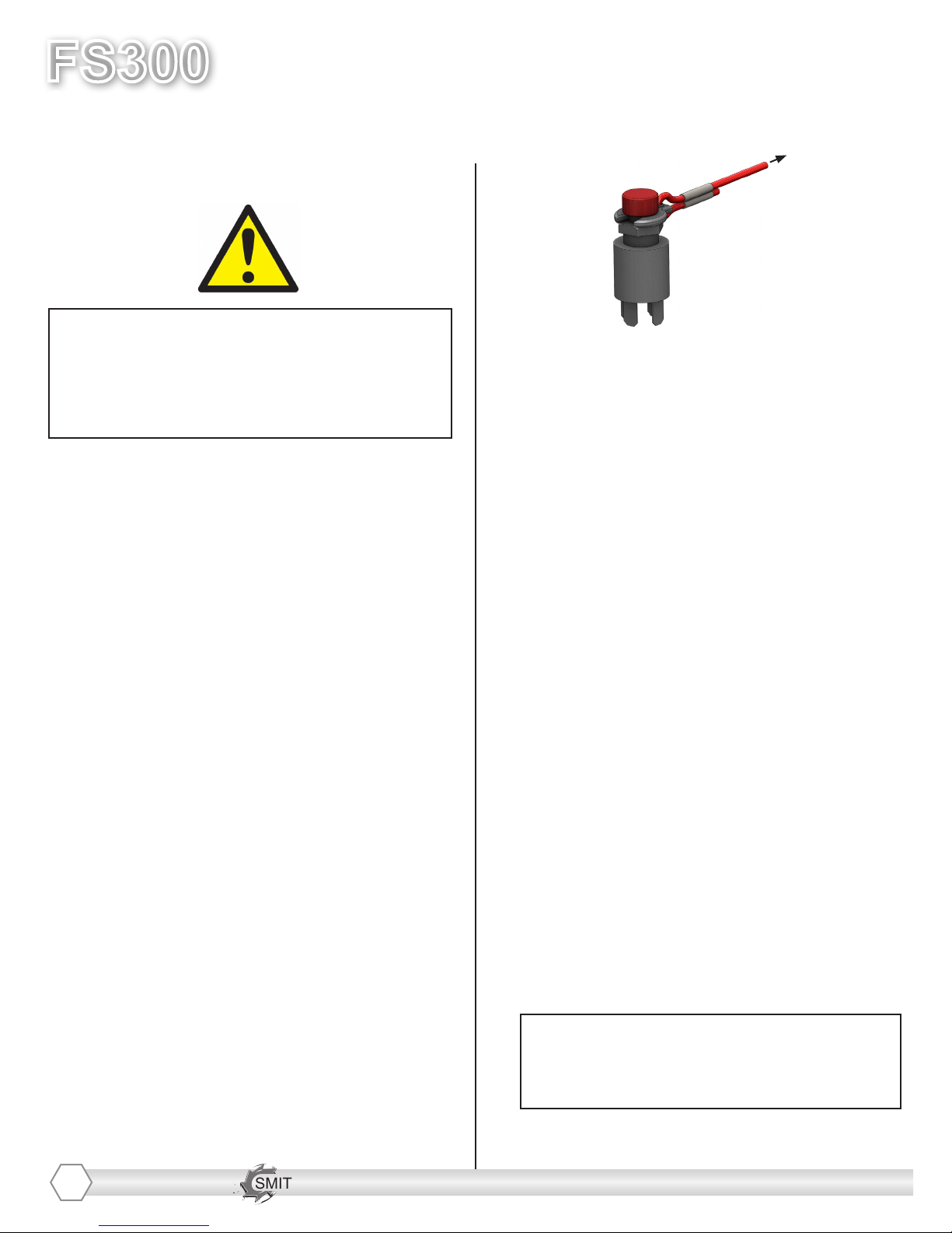
Corded “Engine Kill” Button (not available
on electric motor): In the event of a malfunc-
tion or an accident (such as the machine op-
erator falling or losing footing), the SPS10 is
equipped with a corded “Engine Kill” Button.
Attach the end of the cord to the operator’s
belt or wrist, and snap the clip into place on
the stop switch by raising the top of the Engine
Kill Button and inserting the clip into the gap.
If the operator becomes distanced too far from
the machine, the cord will detach from the stop
switch, and the machine will stop running.
Attatch to
operator
*NOTE: the Engine will not start without the
Corded Engine Kill’s clip securely in place.
CAUTION: The machine will still move with
the engine off.
IF THE ENGINE DOES NOT
START
1) Check Engine for proper gas and oil levels
(refer to Engine manual)
2) Check spark plug. Make sure the socket
areas are clean and clear of debris, and that
the proper gap is set. (Replace if needed).
3) Check Brown Electrical clip hanging on the
front of the engine and ensure that the
electrical wires are making contact within the
clip.
4) Turn the On/Off switch, on the front of the
Engine, to “On”.
5) Check Corded Engine Kill Button’s
Connections:
a) Make sure the Corded Safety Stop “C”
Connector is dipped properly.
b) Try switching the connection to the opposite
post (From letter “C” to letter “M”, for example).
6) Engine may have tilted backwards. If so,
allow oil to drain after removing spark plug and
pulling starter cord several times
*Engine repair and engine warranty
issues are handled directly
by your local engine service center.
6

SMITH Manufacturing 1-954-941-9744 www.SmithMfg.com
VERSION 8/2013
FS300
Gas
7
SUBSTRATE REMOVAL
Warning: Should you desire to tilt the
machine, always tilt forward. Tilting the
machine backwards at any time will ood
the spark plug with oil and may cause
damage to your engine!
Adjust the height of the cutter drum with
the Hand Wheel and Cam Lever. (Turn the
hand wheel to raise the cutter drum off of the
substrate. Lower or raise the cam lever to
engage or disengage the drum after setting
the proper cutter depth.)
Set the deoth of cut to allow the cutters to go
through only the materials to be removed.
Make certain that the drum is positioned to
where only the cutters strike the surface,
and that the drum assembly never comes
into contact with the substrate. The cutter
tips alone should strike the surface (1/8”
to 1/4” maximum depth per removal pass on
new cutters).
The drum will not withstand substrate
contact. Contacting the removal surface
too deeply will cause premature wear to
cutters, shafts, drum and other
components!
Too much downward pressure only has
negative results. Try to remove materials in
several passes rather than one, deep pass.
Several tests will show the best, most
appropriate cutter impact. Use a forward,
backward and/or circular pattern to achieve
your desired nish.
NOTE: Only use a forward motion when the
CM2150 or CM2550 carbide milling cutters
are used.
TIP: Positioning the machine over the
surface in many direrctions, as well as
dialing the hand wheel up or down can help
create desirable surface patterns.
After several hours of practice, the operator
will become comfortable and should be able
to remove materials faster with enhanced
results.
When the job is completed, or the operator
wants to cease work, stop the engine by rst
lifting the drum above the substrate using the
hand-wheel and/or the cam lever. Stop the
machine only at the engine. Then close the
fuel cock to shut off the fuel supply.
The drum assembly must be removed daily
and inspected for drum wear, hole
elongation and possible weld separation.
Replace the cutter shafts and drum bushings
every 40 hours, or prior to any drum wear. If
the drum’s center holes are elongated, oreder
another SMITH cutter drum.

SMITH Manufacturing 1-954-941-9744 www.SmithMfg.com
FS300
VERSION 8/2013
Gas
SMITH Manufacturing 1-954-941-9744 www.SmithMfg.com
STORAGE
Shut off fuel valve and remove all fuel or
add fuel stabilizer. Start engine and run until
it stalls. Remove spark plug and pour two
ounces of motor oil into cylinder and slowly
crank the engine by hand to distribute oil to
prevent rust during storage.Replace spark
plug and store machine upright in a cool, dry,
and well-ventilated area.
ORDERING
To ensure product safety and reliability,
and to maintain your warranty, always use
genuine replacement cutters and partsfrom
SMITH when making repairs to equipment.
When oredering please specify the model and
serial number of the machine. In addition, give
a part number, description, and quantity as
listed on your parts list.
If you have any questions about the operation
of your machine or would like to order
replacement parts, contact your SMITH
Manufacturing representative directly.
Contact 1-800-653-9311 (954-941-9744)
for information.
Visit our website at
www.smithmfg.com
WARRANTY CLAIMS
The manufacturer reserves the right to
change or improve the machine design with-
out assuming any obligation to update any
products previously manufactured before
this manual. It is the customer’s responibility
to complete the warranty card and mail it to
the seller within 10 days from date of pur-
chase. If a failure occurs during the warranty
period, the customer must contact the seller
to determine the appropriate action.
Any and all transportation charges are to
be borne by the purchaser.
8

SMITH Manufacturing 1-954-941-9744 www.SmithMfg.com
VERSION 8/2013
FS300
Gas
TROUBLESHOOTING
PROBLEM
Possible Reason(s)/Solution(s)
CUTTERS WEARING
UNEVENLY/PREMATURELY
Drum is too low
Icorrect set-up
Material Build-up
Cutters too tightly loaded
Wrong cutters for
application
CUTTERS SHAFT BREAKAGE
UNEVENLY/PREMATURELY
Drum is too low
End plates or bushings worn
Shafts worn
Wrong cutter set-up
Over 40 hours service-life
DRUM WEARING
PREMATURELY OR CRACKING
Drum hitting ground
Shafts and bushings not replaced
within 40 hours
EXCESS VIBRATION
Bearing worn
Hex bushing worn
Drive shaft worn
Improper cutter set-up
Drum contacting ground
Wheels worn out
MACHINE JUMPS
ERRATICALLY
Drum hitting ground
RPM is too low
Surface is severely uneven
DRIVE BELT WEARING
PREMATURELY
Pulley is misaligned
Wrong belt
Drum is contacting
the surface
MACHINE WONT MOVE IN
FORWARD OR REVERSE
Check hydraulic reservoir level
Verify v-belt to hydraulic pump
is not slipping or damaged
*Engine repair and engine warranty
issues are handled directly
by your local engine service center.
For any other problems or questions,
please contact your local representative
or
SMITH Mfg today at 800-653-9311
or
(954) 941-9744.
9
Check lifting carriage is in
upright position and drive
wheels in cocntact with ground

SMITH Manufacturing 1-954-941-9744 www.SmithMfg.com
FS300
VERSION 8/2013
Gas
SMITH Manufacturing 1-954-941-9744 www.SmithMfg.com
MAINTENANCE CHECK LIST
Note: Make sure the ignition is in the OFF
position, and the spark plug is disconnected
before servicing
• Maintain proper engine oil and crankcase
levels.
Change every 25-50 hours
(see Honda manual).
• Clean spark plugs regularly, and set the
proper gap.
• Wash the air cleaner element in a non oil-
based solvent, then squeeze out residue.
Allow lter to dry before reinstalling in cleaner.
• Keep a coating of grease on the drive shaft
and threads for easy installation or removal,
and for longer hex bushing life.
• Check all fasteners and re-tighten, since the
machine will vibrate the fasteners loose if they
are not secured. Use locktight.
• Check the Drive belt for wear, and adjust
(tension), or replace as required.
After replacing belts, check for proper tension:
• Adjust Idler to tension belt. Do not over
tighten.
• Check that the pulleys are aligned properly
to ensure the belts are running true.
10
• The inside housing must be clean, and
remove any build-up from inside the cage so
cutters and drum rotate freely.
• Inspect and change drum bushings and
shafts every 40 hours, or when worn.
Ce manuel convient aux modèles suivants
1
Table des matières
Autres manuels Smith Machine de plancher
Manuels Machine de plancher populaires d'autres marques

Nilfisk-Advance
Nilfisk-Advance Advance SC370 17B Manuel utilisateur

Numatic
Numatic ET 4045 Manuel utilisateur

HAWK ENTERPRISES
HAWK ENTERPRISES HP1513-180BRUTE Manuel utilisateur

Mytee
Mytee 8070 Mytee-Lite Manuel utilisateur

Kärcher
Kärcher B 140 R Manuel utilisateur

Triple S
Triple S Ace 26T1 Manuel utilisateur


