912/101 Preparing the arm mounting Board
Where the deck is not already cut to accept an
SME arm, it will need to be prepared as follows:
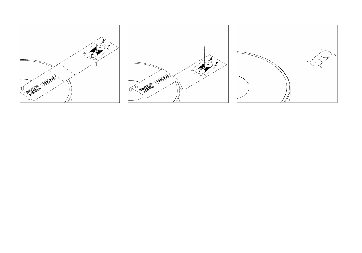
Pierce the centre point A of the mounting
template to accept a pin or needle about 50mm
long. Place the template on the record spindle
and keeping it parallel with the surface on which
the arm will be mounted pass the pin vertically
through the centre point A and spike it into the
pick-up arm mounting board.
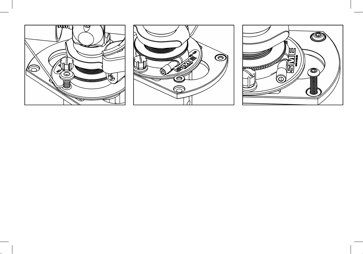
912/102
Disengage the template from the spindle and
maintaining the same alignment slide it down the
pin and onto the mounting board. This will
position the base for maximum effective
movement when adjusting the horizontal
tracking angle (HTA), see 125. Anti-clockwise
rotation from this position up to approximately
40° can be made to meet individual needs but is
not critical provided that the requirements of the
alignment protractor can be satisfied. Note that
the rear overhang requires a 51mm radial
clearance from the point shown on the template.
912/103
Using a scriber or a compass point, spike
through the centre points B and centres of the
four fixing holes. Remove the template and mark
two Ø28mm circles about the points B already
centred. Join these together tangentially with
two parallel lines to complete marking out.
Drill four Ø4mm fixing holes and two Ø28mm
holes. Cut away the remaining area to form a
slot and finish the edges with a file and
glasspaper. If a hole saw is not available chain
drill a series of small holes around the inside of
the line, saw and file out.
With suitable tools and technique the procedure
is similar for materials other than wood.
9
Preparing the Mounting Board
Where the deck is not already cut to accept an
SME tonearm, it will need to be prepared
as follows:
Pierce the centre point A of the mounting
template to accept a pin or needle about 50mm
long. Place the template on the record spindle
and keeping it parallel with the surface on which
the arm will be mounted pass the pin vertically
through the centre point A and spike it into the
tonearm mounting board.
Disengage the template from the spindle and
maintaining the same alignment slide it down the
pin and onto the mounting board. This will position
the base for maximum effective movement
when adjusting the horizontal tracking angle
(HTA). Anti-clockwise rotation from this position
up to approximately 40° can be made to meet
individual needs but is not critical provided that
the requirements of the alignment protractor can
be satised. Note that the rear overhang requires
a 51mm radial clearance from the point shown on
the template.
Using a scriber or a compass point, spike
through the centre points B and centres of the
four xing holes. Remove the template and mark
two Ø28mm circles about the points B already
centred. Join these together tangentially with two
parallel lines to complete marking out.
Drill four Ø4mm xing holes and two Ø28mm
holes. Cut away the remaining area to form a slot
and nish the edges with a le and glasspaper.
If a hole saw is not available chain drill a series
of small holes around the inside of the line, saw
and le out.
With suitable tools and technique the procedure is
similar for materials other than wood.