©2021 EMS Ltd. All rights reserved. Page 6 of 14 TSD127-0001-99 (Issue 1) 05/05/2021 AJM
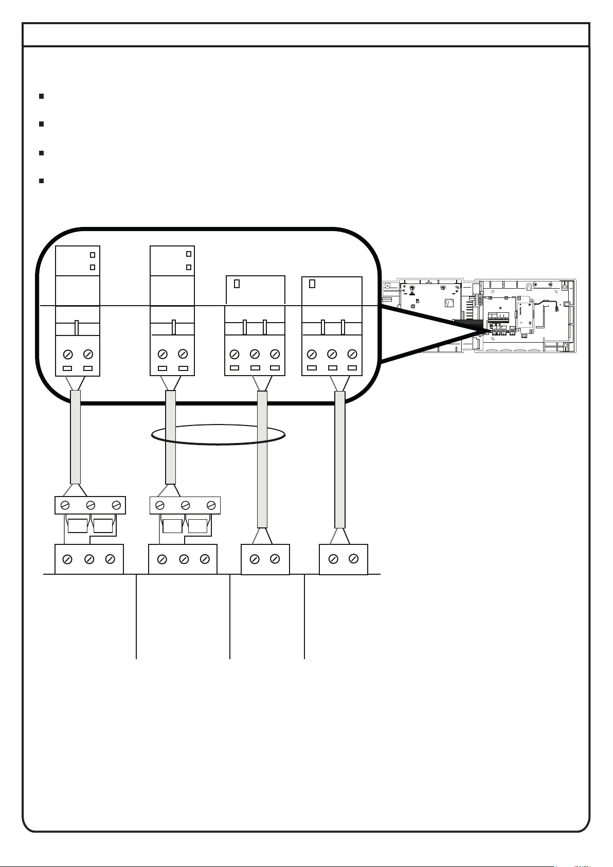
8 Wiring to an addressable fire system
Wire the inputs as shown below, using the resistor pack provided.
If an input is not being used, leave the 20 kΩ resistor as factory fitted.
Both outputs are voltage free and rated 30 V @ 1 A.
The maximum cable length to connected devices is 10 m.
FOOTNOTES
*
†
Optional cabling, required only when the following SmartCell devices are added to the WZM;
detectors, call points and I/O units (I/O units when set to ‘Off When Reset’) - see the SmartCell
WZM Programming Guide (MK067) for more details on this feature.
Wiring can be normally open or normally closed operation as required.
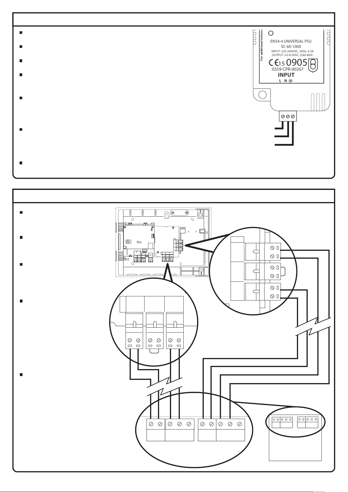
SKIP THIS STEP IF CONNECTING TO A CONVENTIONAL FIRE SYSTEM.
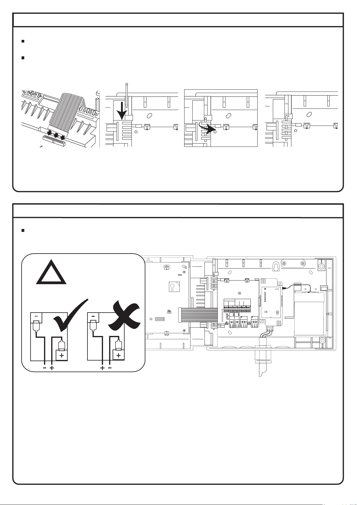
BAT
ENABLE
TAMPER
RESET
AERIALA AERIALB
ATTENTION
ELECTROSTATIC
SENSITIVEDEVICE
RS232
EN54-4UNIVERSAL PSU
SC-60-1000
INPUT:220-240VAC, 50Hz, 0.3A
OUTPUT:5.0-8.5VDC, 0.8A MAX
STATUS
FAULT
MAINS/ CHARGER FAIL
BATTERYLOW
BATTERYFAIL
START
INPUT
L N
Foradditional information refer to TSD042
0359-CPR-00267
15
0905
SLIDETO
REMOVE
EOL
(+) (-) (+)(+) (-) (+) (-) (+) (-) (+) (+) (-)
SOUNDERA
L1 L1 L2 EOL ALARM L1 L1 L2
IN OUT RES IN OUT
ZONE
A B A B NC C NO NC C NO
FIRE
INPUT2
INPUT1 FAULT
FAULT
ACTIVE
FAULT
ACTIVE
A
B
C
D
230 VAC variant shown
NC C NO NC C NO
FIRE FAULT
A B
INPUT1
FAULT
ACTIVE
A B
INPUT2
FAULT
ACTIVE
FAULT INPUT
FIRE INPUT
NO C
FIRE OUTPUT 2
(to clear when
panel reset)
FIRE OUTPUT 1
(to clear when
panel silenced)
NO C NC NO C
Addressable fire system connections
NO C NC
*††
4k720k 4k7
20k