Smappee Infinity Manuel utilisateur
English – Version 2.0 – July 2020
Smappee Infinity
Installation manual

Smappee Infinity – Installation manual – English
2
Table of contents
1. Safety instructions 3
2. Smappee Infinity modularity 6
3. How to install 8
4. Planning and site preparation 9
5. Initial setup and configuration 11
6. Physical installation 12
7. Smappee Cloud connectivity 19
8. Configuration of CTs 21
9. Validation of the installation 22
10. Configuration of Smappee Input module 23
11. Configuration of Smappee Output module 25
12. Troubleshooting 28
13. Smappee Bus cable specification 33
14. Addendum 1 – Colour code explanation 34
15. Addendum 2 – Wi-Fi connection properties and firewall rules 37
16. Addendum 3 – Components overview 38

Smappee Infinity – Installation manual – English
3
1. Safety instructions
Safety warning
Carrying out electrical work in a home or workplace can be dangerous.
The Power Box, CT Hub, Solid Core 3-Phase CT, Current Transformers (CT) and Rogowski coils are
usually installed inside the distribution board under a protective cover. The other components can
be installed both inside and outside the distribution board.
Only certified electricians may carry out the installation, which must be in accordance with the
national safety regulations.
Safety precautions
CAUTION: Risk of electric shock.
CAUTION: Refer to the accompanying documentation whenever you see this symbol.
DO NOT clamp or pull out NON-INSULATED conductors carrying DANGEROUS VOLTAGE
which could cause an electric shock, burns, or arc flash.
Please observe the following safety precautions to avoid potential electric shock, fire, or personal
injury:
• Use this product only for its intended purpose.
• Use the product indoors only.
• Only mount the power cable in a sealed enclosure.
• Locate a free fuse or install an additional fuse for the protection of the Power Box. Connect
the power cable according to the connection diagram, see next pages.
• The circuit breaker acts as the disconnect device and must meet IEC 60947-2
• Do not open the equipment or touch any of its electronic circuitry.
• Do not attempt to open, repair, or service any parts.
• Only use the cables delivered with the product.
• Do not use the product if damaged.
• Do not use damaged current transformers or cables.
• Do not immerse the product in water or any other liquids.
• Do not expose the product to heat, flame, or extreme cold.
Product identification
• Smappee Power Box: MOD-VAC-1
• Smappee CT Hub: MOD-IAC-1
• Smappee Solid Core 3-Phase CT: MOD-IAC-2
• Smappee Genius: MOD-GW-1
• Smappee Wi-Fi Connect: MOD-GW-2
• Smappee Connect: MOD-GW-3
• Smappee Input module: MOD-INP-1
• Smappee Output module: MOD-OUT-1
Smappee Infinity – Installation manual – English
4
Maintenance
• Clean the outside only with a dry, clean cloth.
• Do not use abrasive agents or solvents.
Responsibility
• Assembly, connection, and use must be carried out in accordance with the installation
standards currently in force.
• The device must be installed in accordance with the instructions given in this manual.
• Failure to observe the instructions for installing this unit may compromise the device’s
intrinsic protection.
• The device must be placed in a system that complies with the applicable standards and safety
regulations of the country of installation.
• Cables may only be replaced with cables of the correct rating.
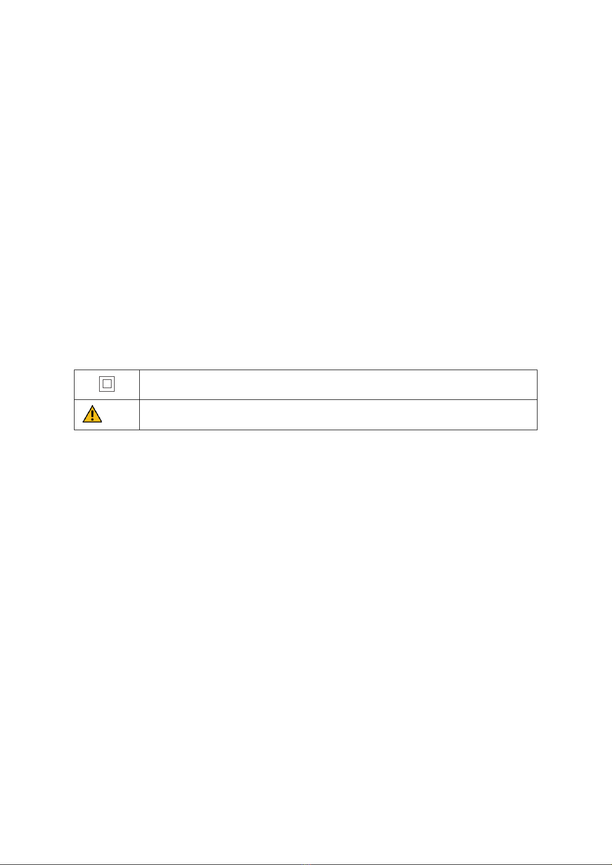
Explanation of the safety symbols
The table below explains the safety symbols.
Class II equipment does not require an earth connection.
IK 06
This device has been tested according to IEC 62262 and complies to impact class 6
(Impact energy: 1 Joule).
Residual safety risk
• The device’s housing has IK06 impact immunity level. Therefore, it is essential that the housing
is not damaged during installation.
• When there is visible damage to the device’s housing, it is recommended to replace the device
to prevent any hazardous situation to occur.

Smappee Infinity – Installation manual – English
5
Support
Only certified electricians or equivalent may install the Smappee Infinity.
If you have any questions, please contact your local distributor.
In case your local distributor is unable to help you, you can contact Smappee at:
Smappee n.v.
Evolis 104
8530 Harelbeke
Belgium
Smappee Infinity – Installation manual – English
6
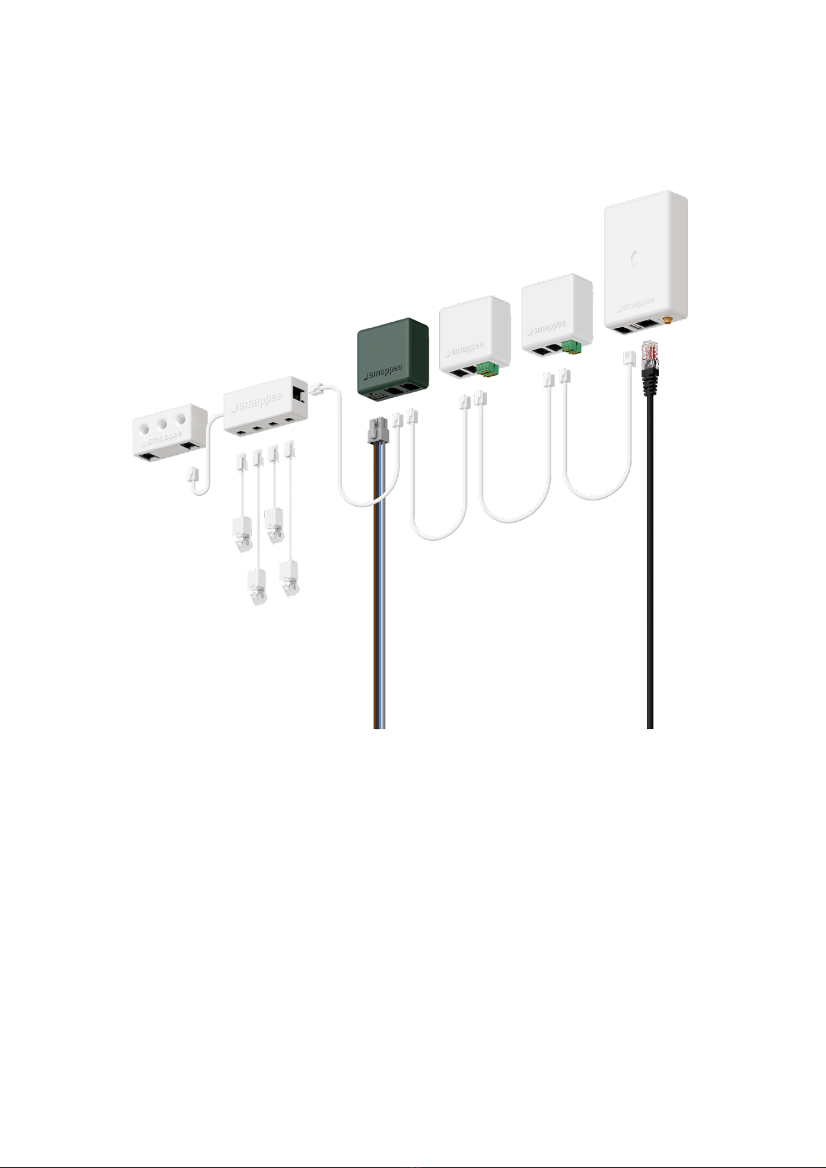
2. Smappee Infinity modularity
Smappee Infinity is an all-in-one energy management system that offers detailed real-time and
historical energy data as well as IoT-enabled control and dynamic load balancing. It monitors solar
PV, home storage, individual or groups of appliances and complex energy consumers such as heat
pumps, air conditioning or electric cars. In addition, it offers intelligent automations that enhance
security, comfort and cost savings. The system is future-proof and can adapt to any scenario,
allowing over-the-air updates and extra modules to be added at any time.
Smappee Infinity is a global solution that is compatible with all inverters and almost any electrical
installation worldwide. Thanks to the compact hardware, it fits easily into almost any distribution
panel. Once the system is up and running, maintenance requires little effort, resulting in a low TCO.
The two-step installation process consists of the physical installation in the distribution panel
followed by configuration via the installation wizard in the Smappee App. The Smappee Dashboard
also allows further configuration. Preparing the set up at your premises prior to carrying out the
physical installation for your customer, saves valuable time.

Smappee Infinity – Installation manual – English
7
A modular solution for every energy need.
The strength of the Smappee Infinity system lies in its modularity, allowing you to mix and match
according to your energy needs. Depending on the setup, Smappee Infinity will gather energy data,
communicate that data to a data platform and, if desired, control the energy flows in the building.
Discover the different Smappee modules for different features and services.
1. Data gathering
The Smappee CT Hub gathers energy data by measuring different currents with up to 4 CTs
or Rogowski Coils. Use the Smappee Solid Core 3-phase CT as a simple and cost-efficient
alternative. Or add a Smappee Input module to count pulses or monitor input status with up
to 4 digital inputs. Add Smappee Gas & Water for detailed data on gas and water
consumption.
2. Communication
The Smappee Genius is the gateway between the Smappee modules and the Smappee Cloud
and ensures secure data storage. It also interacts with Smappee’s controlling modules and
3rd party components. Use the Smappee Connect or Wi-Fi Connect as a cost-efficient
gateway to add communication to the Smappee Infinity.
3. Control
Control (a group of) appliances remotely with the Smappee Switch or with the Smappee
Output module. The Output module can also be used as a control signal for smart devices.
On top of that, you can integrate third party IoT products via the Smappee App. Finally, set
up rules to connect and control these smart devices with the Smappee Automations in the
App.
4. Power supply
The Smappee Power Box measures the line voltage of the connected phases, collects the
currents from the CTs and calculates power, active, reactive and other energy and power
quality data.
The Smappee Infinity is configured through the Smappee Energy Monitor mobile app (which you can
download from the Apple App store or Google Play store). The real-time and historical monitoring
data are accessible for visualisation and analysis purposes.
Smappee Infinity can easily pair with IoT products and platforms such as Nest, Amazon Alexa, Home
Assistant and OpenHab and uses the MQTT and EEBUS communication protocols for even more
integrations. Or simply add a Smappee Switch or Output module to manage any appliance. Discover
pre-defined automations for self-consumption, smart EV charging and overload protection. Our
dynamic load balancing technology directs energy to the HVAC and home battery to provide
additional energy efficiency and peace of mind for you and your customer.

Smappee Infinity – Installation manual – English
8
3. How to install
The installation procedure consists of the following steps:
• Planning and site preparation: to determine the complete monitoring solution.
• Initial setup and configuration: the creation of a location, its properties, and the loads to be
measured.
• Physical installation: the physical installation of all the Infinity components.
• Smappee cloud connection: the selection of internet connectivity and configuration.
• Configuration of CTs
• Validation of the installation: checking the accuracy of live power values.
Optional steps:
• Configuration of Smappee Input module: the configuration of the pulse input sensors.
• Configuration of Smappee Output module: the configuration of the relay outputs.
This procedure is done with the Smappee Energy Monitor mobile app.
1
2
3
4
5
6
7
8

Smappee Infinity – Installation manual – English
9
4. Planning and site preparation
The first step is to determine the complete monitoring solution. This consists of listing all the loads
that need to be measured, their properties, and the required hardware (Smappee and others).
The checklist provided helps you to determine all necessary technical information for the next steps
and also to collect all the necessary hardware.
General architecture - what is to be monitored
Single or multiple metering locations: Where are the fuse boxes or appliances to be
monitored? (Location inside the building, distances between them, etc.).
Total load (main service): Yes/no?
Specific appliances? (e.g. HVAC, Heat pump, EV, Solar, etc.). Are they fused separately or are
they powered by a wall socket & plug?
Circuits (main sockets, lighting area, etc.).
Digital pulse inputs to be measured? (e.g. Gas or Water meter, sensors, etc.).
Any appliance to be controlled? Directly or with a breaker (single or 3-phase).
Details
Topology: Verify the mains voltage – single phase (1P), three-phase 3P+N (3*400) or 3P
(3*230) .
How are the total load, solar, circuits, and/or appliances fused?
Phases of each measured load (circuits and appliances): Single-phase, three-phase, 3P+N
(3*400V) or 3P (3*230V), voltage, frequency, power, amps.
Cross-sectional area or diameter of the wiring.
How will a stable internet connection be provided to the energy monitor: Wi-Fi, Ethernet, or
3G/4G cellular network?

Smappee Infinity – Installation manual – English
10
Tools (not included)
Multimeter.
Screwdrivers.
Wire stripper.
Flashlight.
Needle-nose pliers.
Wire cutter.
Optional: drill, drill bits and screws.
Supplies
(not included)
Cable ties.
Single or three-phase circuit breaker (fuse for Smappee Power Box only).
Ethernet cable in the case of wired communication.
External Smappee Wi-Fi antenna in the case of low Wi-Fi signal.
3G/4G Dongle in case of cellular communication.
Single phase or 3-phase breaker when installing an Output module in combination with a
breaker.
Solid cable with diameter range 0.5 to 1.5 mm² (20 AWG – 15 AWG) when installing an Input
and/or Output module.
Autres manuels pour Infinity
2
Table des matières
Autres manuels Smappee Accessoires audio et vidéo


Manuels Accessoires audio et vidéo populaires d'autres marques

enerserve
enerserve e.manager nD Manuel utilisateur

Starmatrix
Starmatrix Clever-Pool/220V Manuel du propriétaire

TecnoVideo
TecnoVideo VSPT Series Manuel utilisateur

NeoVolta
NeoVolta NV14 Instructions d'utilisation

Horizon Fuel Cell
Horizon Fuel Cell FCJJ-40 Manuel utilisateur

SC&T
SC&T CD108HD Manuel utilisateur


Delta Electronics
Delta Electronics AFE075A43A Manuel utilisateur

Yamaha
Yamaha PTB-4210 Manuel utilisateur

Burst Electronics
Burst Electronics MCG-2 Manuel utilisateur

Panasonic
Panasonic DMP-BD60 - Blu-Ray Disc Player Manuel utilisateur

mind alive
mind alive Smart Manuel utilisateur

MagniLink
MagniLink S PREMIUM 2 MLS-HD-2 Manuel utilisateur