Skyshark P-40N Manuel utilisateur
Skyshark R/C Corporation
1924 N. Pima Drive • Lake Havasu City, AZ 86403, U.S.A.
Ph ne: (928) 854-6100 • T ll Free: 1-866-854-6100
Fax:(928) 854-6111
Website: www.skysharkrc.c m
email: [email protected] m
Features:
• Heavy duty fiberglass fuselage with molded panel lines
• Balsa and ply wing covered and painted
• Pin hinges for all control surfaces
• Hand Painted fiberglass cowl
• Quality USA made 4-40 hardware included
• Extra-heavy duty fiberglass accessories
• Designed for retracts on main and tail
• Instrument panel kit
• 5-1/2” Machined aluminum spinner
• Quick-Align engine mounting system
Spe ifi ations:
Wingspan:........ 82 inches
Length:............. 71 inches
Wing Area:....... 1190 Sq. in.
Weight:............. 19 - 23 lbs
Engine:............ 45 - 65cc gasoline
Radio:.............. 6 channel minimum
Scale: .............. 1/5.5

Thank you for purchasing the P-40N ARF from Skyshark
R/C. For the first time, R/C enthusiasts have a choice in
good quality scale aircraft designs. Good looks and flying
characteristics, and a uniqueness that is sure to turn heads
wherever you take your airplane
Covering
When you receive the P-40, there will normally be some
loose or wrinkled covering. This is due to climate changes
that take place during shipping. The parts are covered in
low temperature Solartex so they don’t require a lot of heat
to remove wrinkles. The best way to tighten the covering is
with a heat gun set for low heat. Hold the gun about 6”
away from the covering and move it in fast circles around
the parts. Be careful, too much heat in one place at one
time will damage the covering or paint.
The Skyshark P-40N is painted with fuel proof 2-part paint.
We have tested it using 25% nitro and standard gasoline. If
you would like to do additional weathering and detailing,
we have found that it is compatible with most other fuel
proof paint. If you plan to add details, we recommend you
use a piece of the canopy that was cut off to ensure paint
compatibility.
CAD Design
CAD design allows strength to be built into the airplane
without sacrificing weight. Because of this, we were able to
make the P-40 lighter than most current airplanes of this
type.
Plastics and Fiberglass
The cowl is accurately reproduced in fiberglass and paint-
ed to match the fuselage. The shark mouth is hand painted
using fuel proof paint. Engines should be mounted invert-
ed to best hide them and for adequate cooling. The canopy
is accurately reproduced in clear plastic and painted to
match. Use care when trimming the canopy because the
paint makes them fragile. Use a canopy scissors to trim
close to the lines, then us a rotary sander to remove the
rest.
Engine Options
Engine choices range from 45 - 65cc. We used a Zenoah
G45 and Revolution 50 in our prototypes. Balance was
right on with either engine but the cowl had to be cut away
in order to fit the Zenoah carb and exhaust.
Cockpit Detail
A fully detailed laser cut and engraved instrument panel is
included in the kit. It does require some simple assembly
but detailed instructions are provided.
Repairs and Replacement Parts
Repairs can be made easily using readily available ply-
wood, balsa and Solartex or other fabric type covering.
Matching paint can be purchased from us. If you would like
to purchase replacement parts, please call our customer
service line at 1-866-854-6100. We will be happy to assist
you with anything that you need.
General Building Information
The Skyshark P-40 was designed to be assembled and
flown by someone with previous giant scale airplane expe-
rience. This instruction manual may leave out some basic
steps that are common to all model airplane assembly.
Please read the manual completely before beginning
assembly. Once you begin assembly, you will not be able
to return the plane for a refund if you decide it is too diffi-
cult.
Occasionally hints will be included at certain building
steps. These are not required for completion, rather they
are tips intended to ease a particular process.
All hardware needed to complete the P-40 is included in the
kit. The pushrods and clevises are 4-40. The other hard-
ware is USA made in SAE sizes. If you need replacements,
any 4-40 clevises or pushrods will work.
We have flown this plane using 60 oz. in. servos in the
ailerons, flaps and elevators without any problems. If you
feel more comfortable, you are welcome to use servos with
higher torque ratings. A high torque metal gear servo
MUST be used on the rudder.
This aircraft is not a toy. It must be flown in a responsible
manner according to the rules set forth by the Academy of
Model Aeronautics. The builder assumes the responsibility
for the proper assembly and operation of this product.
Skyshark R/C shall have no liability whatsoever, implied or
expressed, arising out of the intentional or unintentional
neglect, misuse, abuse, or abnormal usage of this product.
Skyshark R/C shall have no liability whatsoever arising from
the improper or wrongful assembly of the product nor shall
it have any liability due to the improper or wrongful use of
the assembled product. Skyshark R/C shall have no liabili-
ty for any and all additions, alterations, and modifications of
this product.
Before beginning assembly: Check all components for
shipping damage. Be sure to look inside the fuselage and
wings at the servo bay locations for any hidden damage. If
you notice any damage, notify us immediately for replace-
ment parts. Also check all formers inside he fuselage o
insure hey are secured properly o he fiberglass. If you
find any weak areas, sand the area and use 5 min epoxy to
secure the formers. You can also add some 1 oz. fiberglass
cloth for extra reinforcement. This is especially important in
the firewall and tail gear area.
Having said that mouthful, it’s time to start building the best
airplane on the market
1

I ems needed o comple e your P-40N ARF:
Thin CA glue
Medium CA glue
Thick CA glue
5 minute epoxy
30 minute epoxy
Epoxy brushes
Red threadlocking compound
RC-56 canopy glue
Masking tape
Fuel Tubing
EZ fueler or fueling dots
Rubber Bands
Misc. tools for building including: Screwdrivers, hex
wrenches, pliers, scissors, sandpaper, files, etc.
Battery
Retractable main gear (Sierra Giant Scale or other)
Retractable tail gear (Sierra Giant Scale or other)
Air control kit
(2) 5.5” Heavy duty main wheels
(1) 2” Heavy duty tail wheel
(2) Standard servos (throttle & retract valve)
(6) High torque servos (61 oz. or higher)
(1) High torque metal gear servo (120 oz. or higher)
(7) Extra long servo arms
(2) 12" Servo extensions
(5) 24” Servo extensions
(2) Sullivan S517 pushrods (optional center servo)
(1) 4-40 Pull-pull setup (option center servo)
(1) Tru-turn spinner adapter to fit your motor
Y-harness - up to 4 (optional)
Fl ing:
None of the prototypes weighed over 21lbs., though the
weight range specified allows for more individual varia-
tions.
Ground handling is typical of any short coupled airplane.
Advance the throttle slowly and be sure to stay on the rud-
der or you will experience ground looping.
There is nothing out of the ordinary to note about takeoffs.
Advance the the throttle slowly and let the plane build up
speed. It will lift off with very little elevator input. Be careful
while using the rudder in the air. Too much rudder will
cause the plane to stall and go into a spin.
Landings should be done with a low throttle setting and
flaps. Be careful not to use too much rudder on landing or
the plane will tip stall. The best way to land is line the plane
up and let it drift down while keeping a slow throttle setting.
Use as little rudder as possible to keep the airplane flying
straight. The wing is designed to help reduce tip stalls at
lower speeds. Due to this, the Skyshark P-40 can be land-
ed a little slower than most other P-40s in this size range.
Be careful of too much landing speed or the plane will nose
over once the wheels touch the ground.
Windy conditions: Do not attempt to fly in a high crosswind
unless you are very comfortable with the characteristics of
the plane. In the air, you won’t notice the wind but during
landing, the airplane will tend to weathervane and require a
lot of rudder. (see my previous rudder on landing warning )
Landing in head wind is no problem and is actually pre-
ferred
Notes:
2
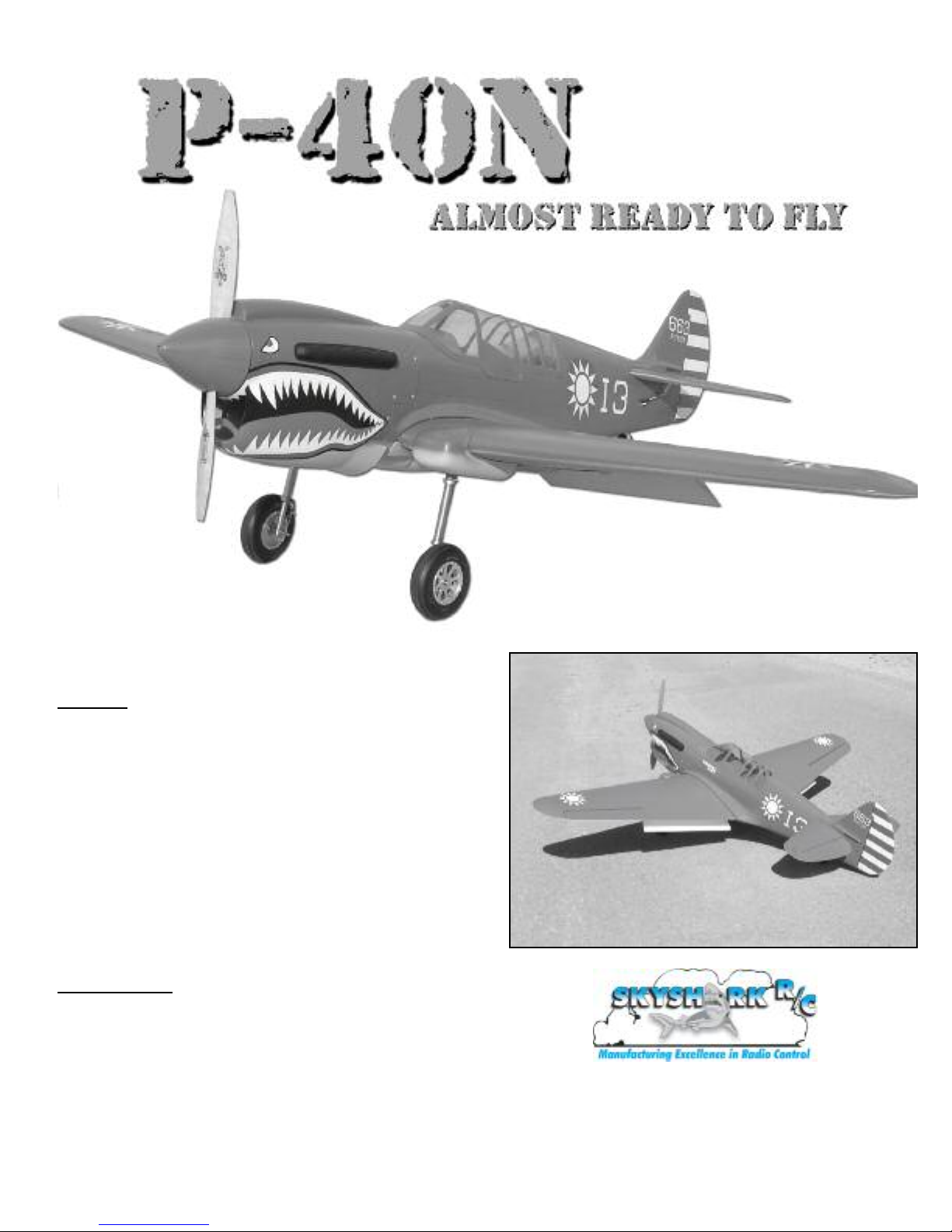
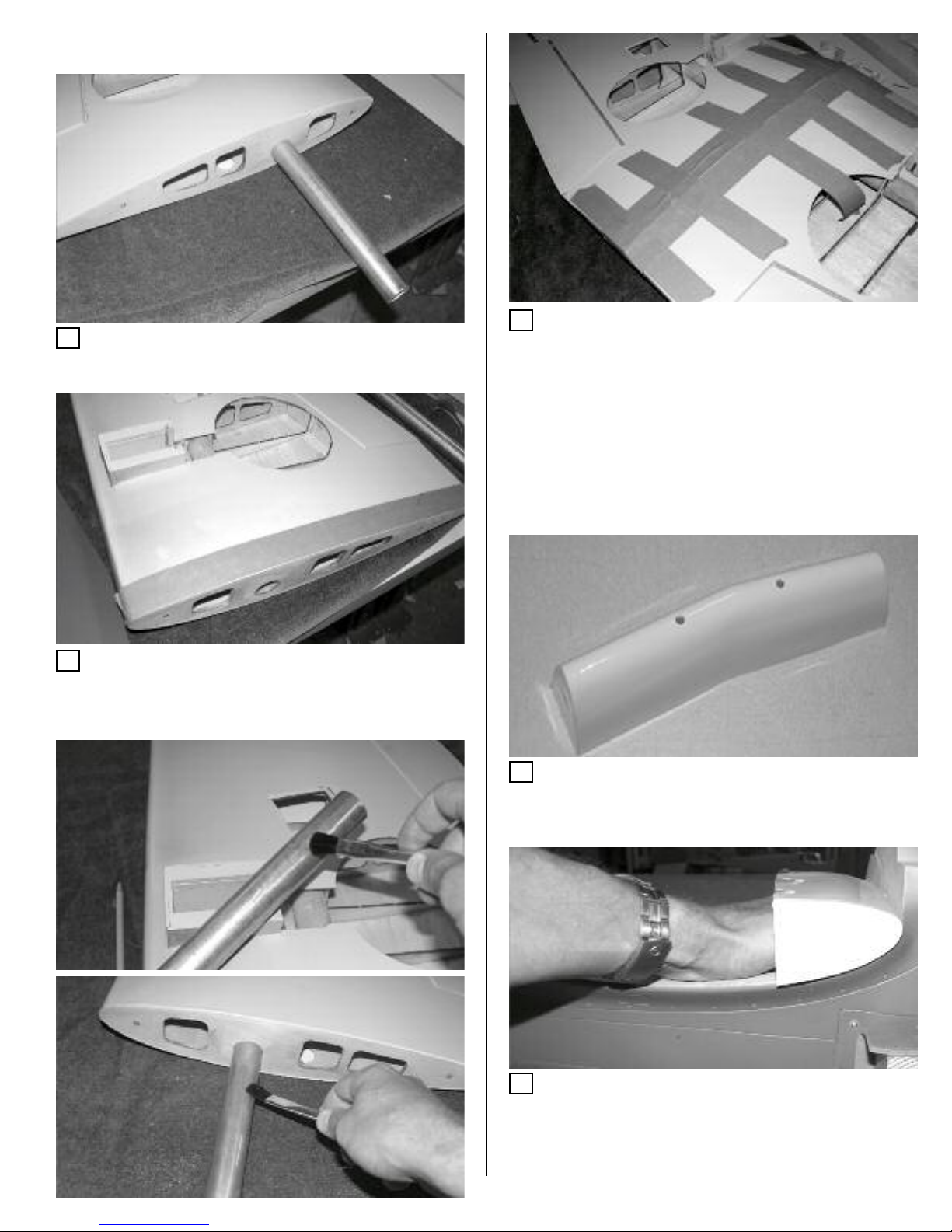
1. Move your hand over the bottom of the wing surface to locate the
wing cutouts for the servo trays and wheel wells. Remove the cover-
ing in those areas using a hobby knife.
3
Note: All ontrol surfa es are pre-hinged, however, the hinges are
not glued in pla e. All hinges should be glued in pla e using high
quality epoxy or Pa er Hinge glue.
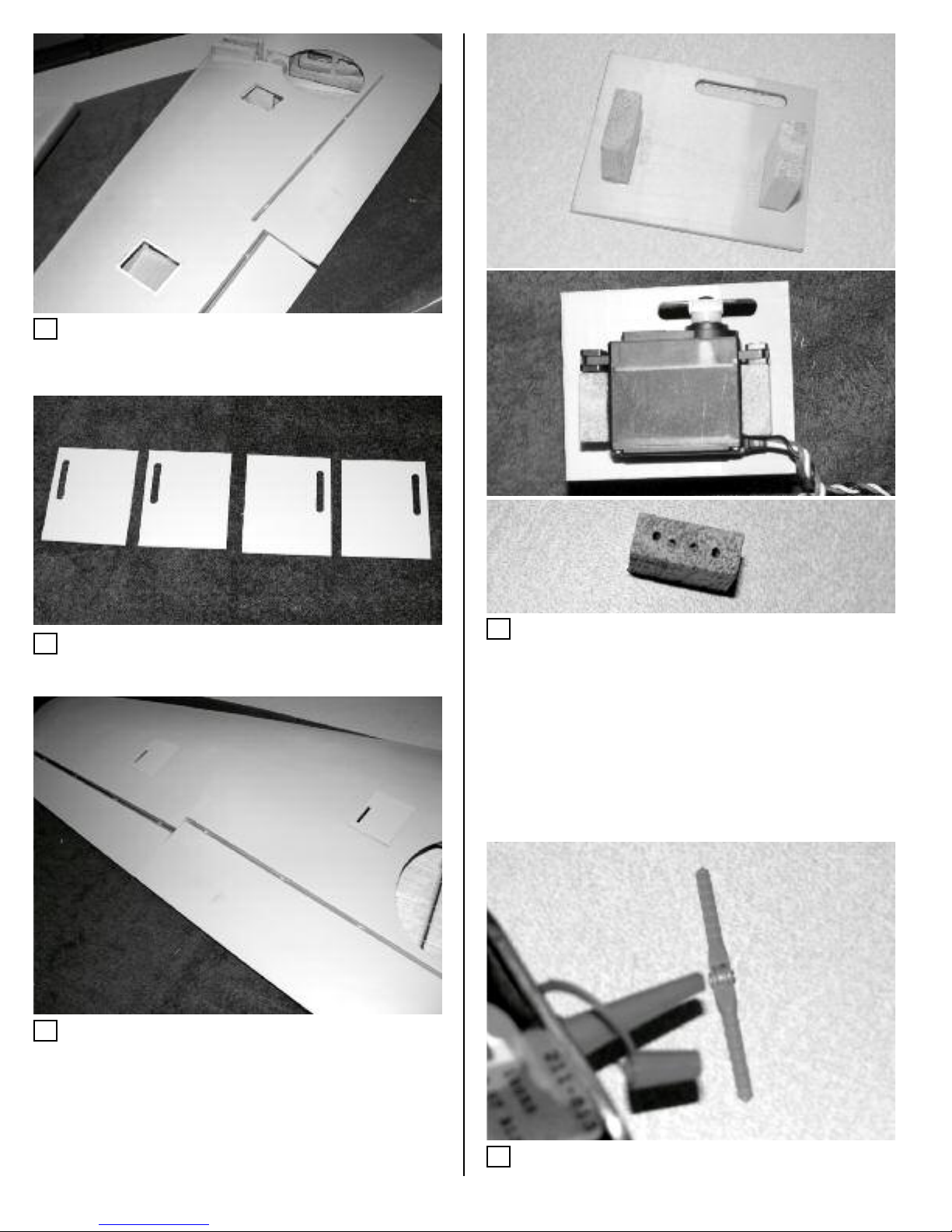
2. Locate the 4 wing servo covers and remove the covering from the
slots using a sharp hobby knife.
3. Test fit the servo covers in the wing holes. The slots in the wing
covers should be positioned as shown in the photo. This will insure
that the pushrods line up with the hardwood blocks in the ailerons
and flaps.
4. Align the servo on the servo cover so the arm is centered in the
slot. Glue the mounting blocks to the servo cover as shown using 5
min epoxy. Note: you can also drill some small 1/16" holes in the
blocks on the side that attaches to the cover. This will help the epoxy
bond better.
Mount the servos as shown. Use long enough servo arms so you will
clear the top of the servo hatch by 1/2” min.
5. Remove the flaps and place a drop of oil on the joint of each
hinge. This will keep the epoxy from getting into the hinge joint when
they are glued in place.
To make servo mounting easier and more se ure, you an use
Sierra Giant S ale P112 aluminum servo mounts. These are avail-
able from Skyshark or Sierra Giant S ale.
4
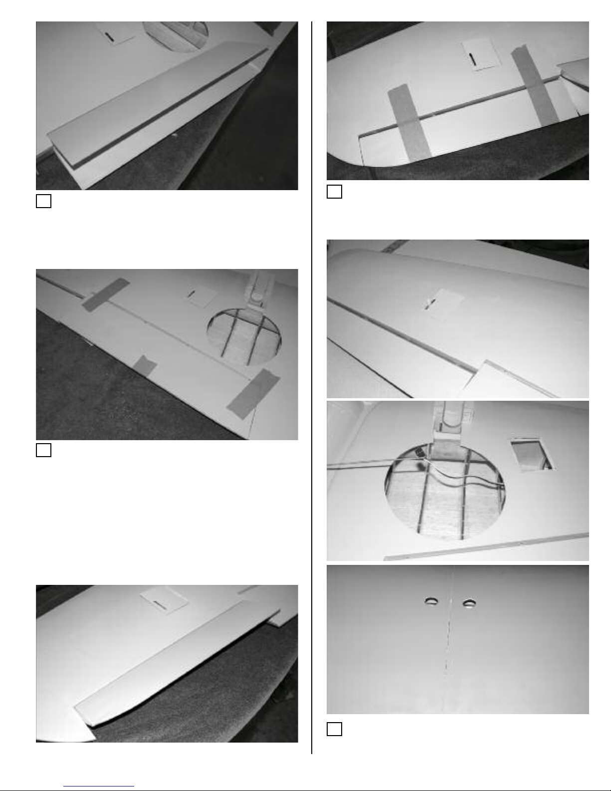
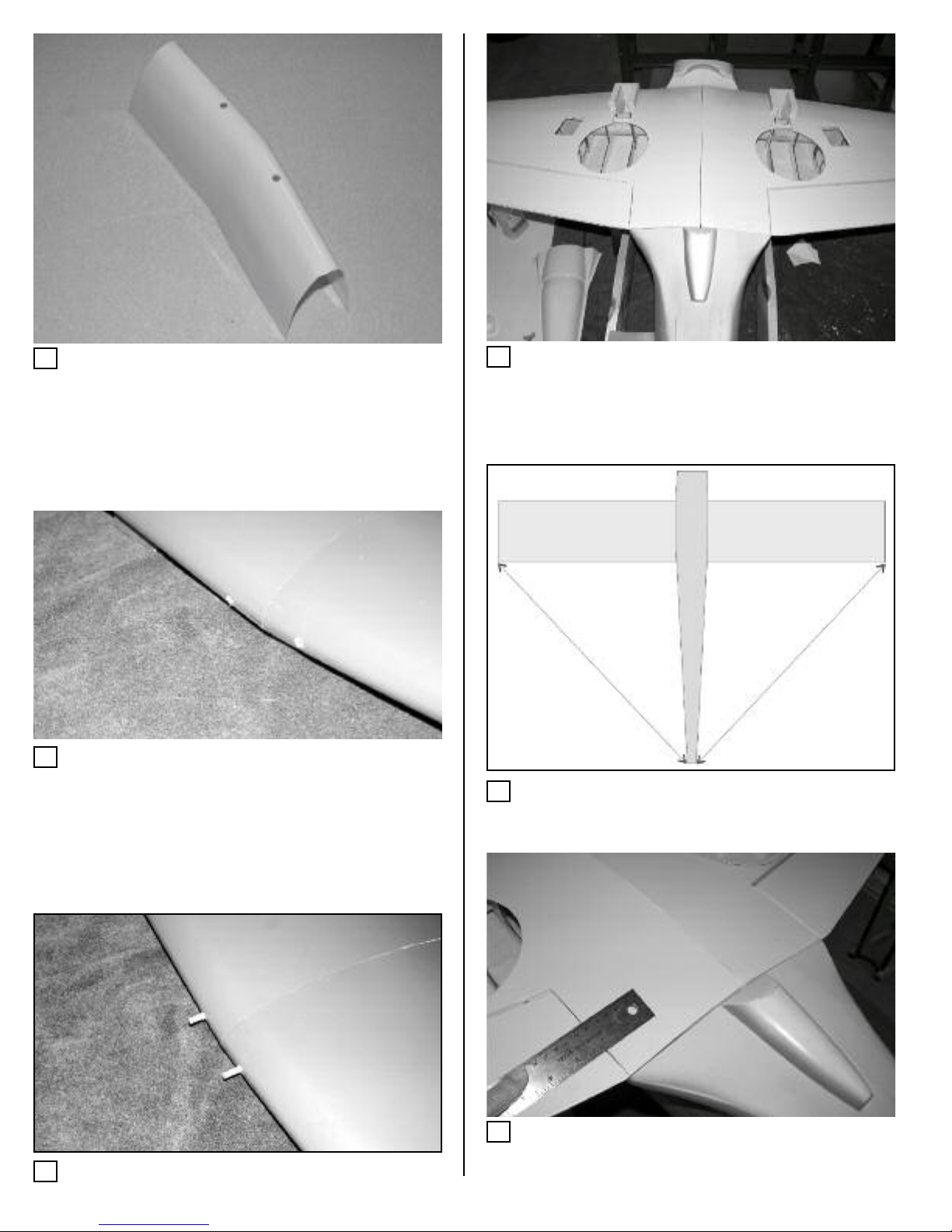
6. Insert the hinges into the flap and trailing edge of the wing. Check
for proper alignment and operation of the flap. Realign the hinges as
necessary. Note: The hinges will be inset into the flap leading edge
so the gap will be minimized.
7. Apply a small amount of 5 min epoxy to one side of each hinge
and insert the hinge into the flap. Apply a small amount of epoxy to
the other side of the hinge. Insuring the hinges operate in the correct
direction, insert the flap/hinge assembly into the holes in the wing
trailing edge. Tape the flap in place and allow the epoxy to dry. There
should less than a 1/16" gap between the flap and trailing edge of
the wing.
Repeat the above process for the other flap.
8. Install the aileron hinges using the same method as the flaps.
Note: The hinge joint will be inset in the aileron leading edge in order
to minimize the gap. There should be less than 1/16” gap when
attached.
9. Connect a 12” extension to the aileron servo and place the servo
in the hatch as shown. Use a long piece of wire to fish the servo
extension through the wing and out the hole in the top center of the
wing. You can locate the wing hole by looking through the end rib.
5
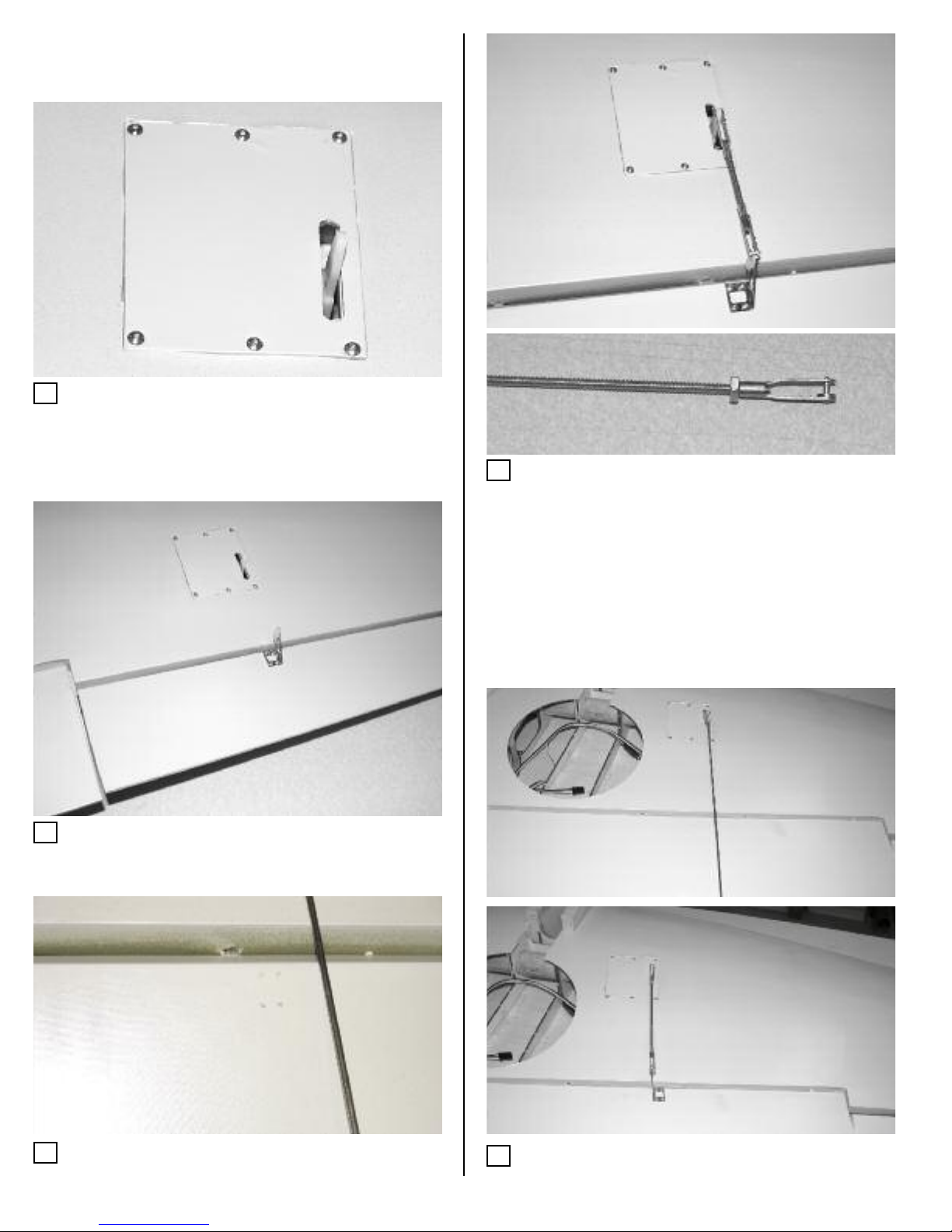
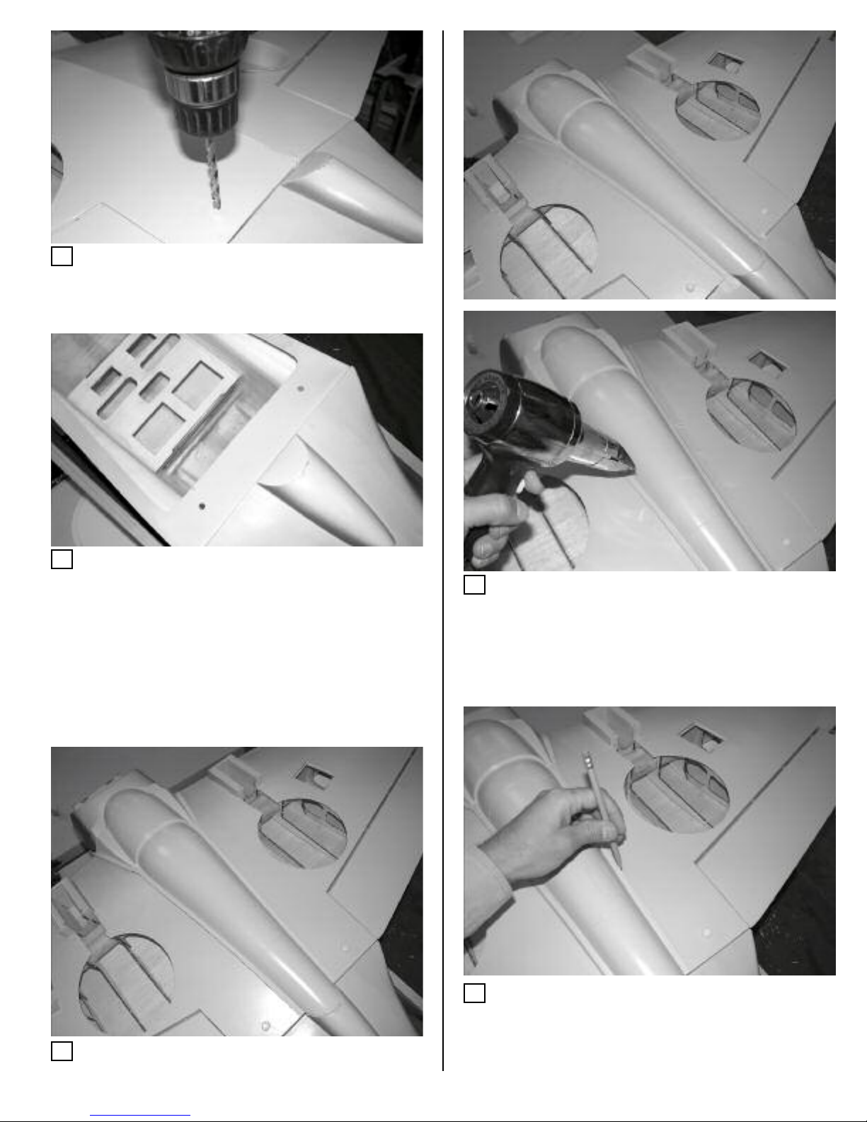
10. Use a 1/16” drill bit to drill holes in the servo hatch and mounting
plate as shown. Make sure to drill close enough to the edge of the
hatch so you also drill into the mounting blocks below. Secure the
hatch using (6) #2 x 3/8” button head screws.
Repeat for the other aileron and flap servo hatches.
11. Locate a 3/4” metal control horn on the aileron by using a
pushrod to align it with the servo arm. The control horn should be
located where the leading edge bevel begins. There will be a hard-
wood block in the correct location.
12. Mark the location of the control horn. Remove the horn and drill
four 3/32” holes at the marked locations. Use the enclosed 2-56 x
1.5” screws to attach the control horn to the elevator and backplate.
13. With the control surface centered attach a 4-40 clevis to the servo
arm and control horn. Measure and cut a piece of 4-40 threaded rod
to the correct length. You can either solder one clevis onto the con-
trol rod or use the enclosed 4-40 nuts to secure them onto the
pushrod. If you don’t solder, use thread locker to secure the locknuts
in place once they are tight against the clevis.
14. Connect the control rod assembly to the servo arm and clevis.
Adjust for proper centering and movement of the control surface.
Note: You may need to enlarge the holes in the servo hatch for full
control surface deflection.
15. Repeat for the other aileron.
Before fastening the servo hat hes in pla e, it’s a good idea to
make sure the servos are properly entered and the arms are in the
orre t position for maximum ontrol movement.
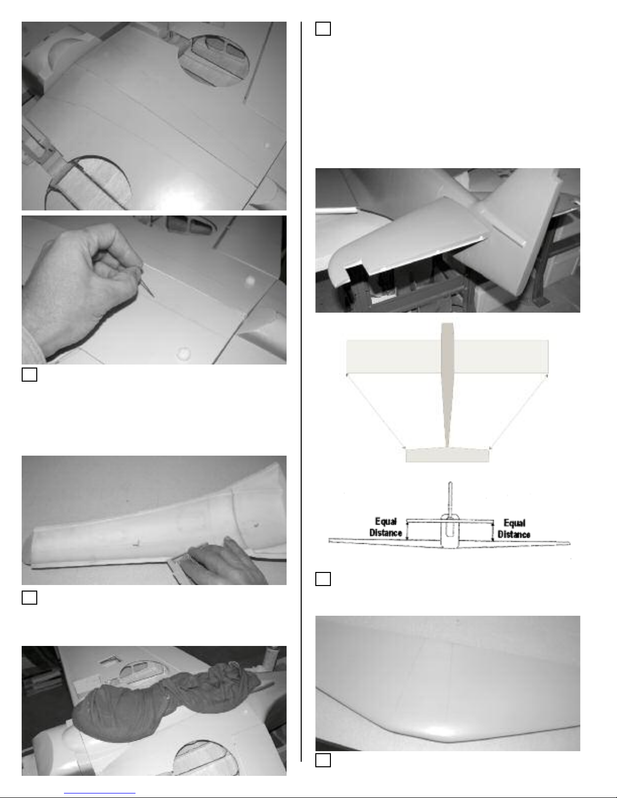
16. Repeat the same procedure for the flap controls. Be careful when
drilling into the flap so that you don’t drill through the top of the wing
6
17. Fit the aluminum tube in the wings and assemble the wing halves
to check for a good fit. Sand or adjust the root ribs as necessary so
there are no gaps.
18. Apply masking tape around the root ribs of each wing half in
order to keep epoxy from getting on the wing when the wings are
assembled.
21. Once the epoxy has cured, locate the leading edge wing dowels
by using the enclosed template. Using a hobby knife, cut two 1/4”
holes in the front of the template at the molded locations.
22. Place the template onto the fuselage so the crease is facing up.
Make sure it is flush against the wing saddle and with the front dowel
mounting plate. Mark the location of the wing dowel holes. Be care-
ful not to flex the template when marking the hole or the wing will not
align correctly.
Wing Joining
19. Apply a light coat of 30 min epoxy to one half of the wing tube
and slide into one wing half. Apply epoxy to the other end of the tub
and to both root ribs.
20. Join the wing halves, making sure that they are parallel and there
are no gaps. Wipe off any excess epoxy with denatured alcohol.
Secure the wing halves with masking tape and set aside to dry.
7
23. Cut off the sides of the template at the molded lines.
24. Fit the template to the leading edge of the wing and mark the
hole locations. Remove the template and drill two STRAIGHT 1/4”
holes at the marked locations.
25. Use 5 min epoxy to glue the wing dowels into place. Insure the
dowels extend 5/8” from the wing leading edge.
26. Place the wing on the fuselage and double check the wing dowel
alignment. Once everything is aligned, drill two 1/4” holes in the
fuselage wing dowel plate at the marked locations.
27. Align the wing to the fuselage as shown and mark its location.
28. With the wing centered, measure 2-1/2" over from the flap and 1"
up from the wing trailing edge. Make a mark in this location on each
wing half.
8
29. Drill a ¼" hole through the wing and wing mounting plate at the
marks made in the previous step. Insure the drill is straight and the
wing is aligned and held securely in place.
30. Enlarge the fuselage wing mounting plate holes to 19/64" and
install the 1/4-20 metal blind nuts securely on the back side using CA
or epoxy. Note: Do not use the nylon 1/4-20 bolts to set the blind
nuts in the plywood because they are not strong enough. The best
way is to use a spare 1/4-20 metal bolt or strong pliers.
31. Bolt the wing to the fuselage and test fit the belly pan to the cen-
ter of the wing bottom
32. If your belly pan doesn’t fit exactly (turned up edges, wrong con-
tour, etc) you can adjust it by taping the edges with masking tape
and using a heat gun to soften the fiberglass while carefully pressing
it into place with a gloved hand. You may need to go over it a cou-
ple times, letting is cool in between. Note: Be careful not to bend the
fiberglass too much while it is cool or the paint will crack.
33. Once you have a good fit, remove the tape on one side of the
belly pan and mark a line on the wing at the edge of the belly pan.
Repeat for the other side.
Belly Pan Mounting: The belly pan is made using very heavy duty
fiberglass and is very inflexible. We made it extra rigid so it won’t
ollapse if you lift the plane by the belly pan or have a gear up land-
ing. Due to this, every belly pan may not mat h the wing ontour
exa tly. We have listed some steps to make for a better fit.
9
34. Remove the belly pan and use a pin to poke holes in the cover-
ing along the inside of the lines you just made.
If you feel more comfortable, you can, instead, remove the covering
along the lines. We use the pin hole method because it’s difficult to
align the small lip on the belly pan exactly to the cut lines.
35. Sand the edges of the belly pan with 100 grit sandpaper to
remove any mold release or high spots and clean with rubbing or
denatured alcohol. Also clean the wing with denatured alcohol in the
area that was marked in the previous steps.
36. Apply 5 or 30 minute epoxy to each mounting edge and fit the
belly pan to the wing. Apply weight to the belly pan until the epoxy
has cured. We use socks filled with lead shot for this task but maga-
zines or plastic bags filled with sand also work.
37. Once the epoxy has cured, you can seal the edges with a fillet of
epoxy. You can also re-heat the fiberglass with a heat gun to make
any stray edges lay smoothly against the wing.
Cut 2” off each end of the plywood wing bolt mounting plate and
align the holes in the plate to the bolt holes in the bottom of the wing.
Epoxy each plate over the wing holes to reinforce the bolt area.
38. Insert the horizontal stab into the fuselage slot and align it with
the wing as shown in the diagram
39. Draw a line on each side of the stab where it meets the fuselage.
Do this on the top and bottom of the stab.
Tail Surfa es
Table des matières
Autres manuels Skyshark Jouet


