Skyetek SKYEMODULE M1 Mode d’emploi

SKYEMODULE M1
ANTENNA DESIGN GUIDE
VERSION 100112

SkyeModule M1 Antenna Design Guide Page | 2
Skyetek Inc
1525 Market St. Ste 200
Denver, CO 80202
www.skyetek.com
Main 720.328.3425 Fax:720.228.2400
COPYRIGHT INFORMATION:
Copyright 2012 SkyeTek, Inc., 1525 Market St. Suite 200, Denver, Colorado 80202, U.S.A. All rights reserved.
Version 100112
This product or document is protected by copyright and distributed under licenses restricting its use, copying, distribution, and decompilation. No
part of this product or document may be reproduced in any form by any means without prior written authorization of SkyeTek and its licensors, if
any.
TECHNICAL SUPPORT AND CONTACT
INFORMATION
SkyeTek, Inc.
1525 Market Street. Suite 200
Denver, CO 80202
http://www.skyetek.com
SALES:
TECHNICAL SUPPORT:

SkyeModule M1 Antenna Design Guide Page | 3
Skyetek Inc
1525 Market St. Ste 200
Denver, CO 80202
www.skyetek.com
Main 720.328.3425 Fax:720.228.2400
TABLE OF CONTENTS
1About this Document ............................................................................................... 6
1.1 Revision History ............................................................................................... 7
2Overview.............................................................................................................. 8
2.1 Internal Antenna .............................................................................................. 9
2.2 External Antenna .............................................................................................. 9
3Custom Antennas ...................................................................................................11
3.1
Design Procedure
............................................................................................11
3.1.1
Example 1
...............................................................................................12
3.1.2 Example 2 –The Internal Antenna of the M1......................................................12
3.1.3 Example 3 –Copper Tape External Antenna.......................................................13

SkyeModule M1 Antenna Design Guide Page | 4
Skyetek Inc
1525 Market St. Ste 200
Denver, CO 80202
www.skyetek.com
Main 720.328.3425 Fax:720.228.2400
LIST OF FIGURES
Figure 1-1: Example Prototype Antenna .............................................................................. 6
Figure 2-1: Antenna Connector ......................................................................................... 8
Figure 2-2: The SkyeRead EA1 External Antenna .................................................................... 9
Figure 2-3: The SkyeRead EA1 Circuit ................................................................................10
Figure 3-1: Example Antenna Layout .................................................................................13
Figure 3-2: Improved Antenna with Ground Shield .................................................................14
Figure 3-3: Design antenna on metal .................................................................................15
Figure 3-4: Points A and B shown......................................................................................15

SkyeModule M1 Antenna Design Guide Page | 5
Skyetek Inc
1525 Market St. Ste 200
Denver, CO 80202
www.skyetek.com
Main 720.328.3425 Fax:720.228.2400
LIST OF TABLES
Table 1-1: Revision History .............................................................................................. 7
Table 2-1: J2 Pin Descriptions .......................................................................................... 8

SkyeModule M1 Antenna Design Guide Page | 6
Skyetek Inc
1525 Market St. Ste 200
Denver, CO 80202
www.skyetek.com
Main 720.328.3425 Fax:720.228.2400
1About this Document
The SkyeModule M1 is designed for low power RFID applications that require less than 4 inches of read
range when using the internal antenna of the M1. Alternatively, the M1 can directly drive an
external antenna to provide up to 10 inches of read range. For applications that require more than 10
inches of read range, a power amplifier can be used to drive an external antenna.
The SkyeModule M1 comes with an integrated internal antenna. The M1 will also work with standard
external antenna modules, such as the SkyeRead EA1. However, many customers will need to
design custom external antennas to best fit their specific application requirements.
SkyeTek and its partners also provide custom RFID antenna design services.
Figure 1-1: Example Prototype Antenna

SkyeModule M1 Antenna Design Guide Page | 7
Skyetek Inc
1525 Market St. Ste 200
Denver, CO 80202
www.skyetek.com
Main 720.328.3425 Fax:720.228.2400
1.1 Revision History
Revision
Author
Change
100112
Brad Alcorn
Releasing new format with minor edits.
Table 1-1: Revision History

SkyeModule M1 Antenna Design Guide Page | 8
Skyetek Inc
1525 Market St. Ste 200
Denver, CO 80202
www.skyetek.com
Main 720.328.3425 Fax:720.228.2400
2Overview
This antenna design guide provides some basic theory as well as several practical examples of how
to design high performance cost effective RFID antennas for use with the SkyeTek M1 RFID reader
module.
All antenna connections are made at the Antenna Connector J2.
Figure 2-1: Antenna Connector
J2
Pin
Name
Description
1
GND
Antenna Ground.
2
ANT
Antenna Output pin. ANT provides 50 ohms output for matching an
external antenna. Jumper ANT to INT to enable the on-board antenna.
3
INT
Internal Antenna pin. Jumper INT to ANT to enable the on-board
antenna. Remove the jumper between INT and ANT to disable the on-
board antenna and connect an external antenna.
Table 2-1: J2 Pin Descriptions

SkyeModule M1 Antenna Design Guide Page | 9
Skyetek Inc
1525 Market St. Ste 200
Denver, CO 80202
www.skyetek.com
Main 720.328.3425 Fax:720.228.2400
Using an oscilloscope, the typical waveform at ANT of the M1 can be observed. It should look like
a 13.56MHz sine wave, approximately 10Vpp. Note that typically the antenna drive signal at the ANT
pin of J2 is generated when a host first sends a tag command to the M1 in which the RF_F is set (see
SkyeTek Protocol V2 Guide for more details on RF_F).
2.1 Internal Antenna
The internal antenna of the SkyeModule M1 provides 70mm read range and 100mm x 100mm read
coverage. Connect ANT to INT to enable the internal antenna.
2.2 External Antenna
Figure 2-2: The SkyeRead EA1 External Antenna
SkyeModule M1 Antenna Design Guide Page | 10
Skyetek Inc
1525 Market St. Ste 200
Denver, CO 80202
www.skyetek.com
Main 720.328.3425 Fax:720.228.2400
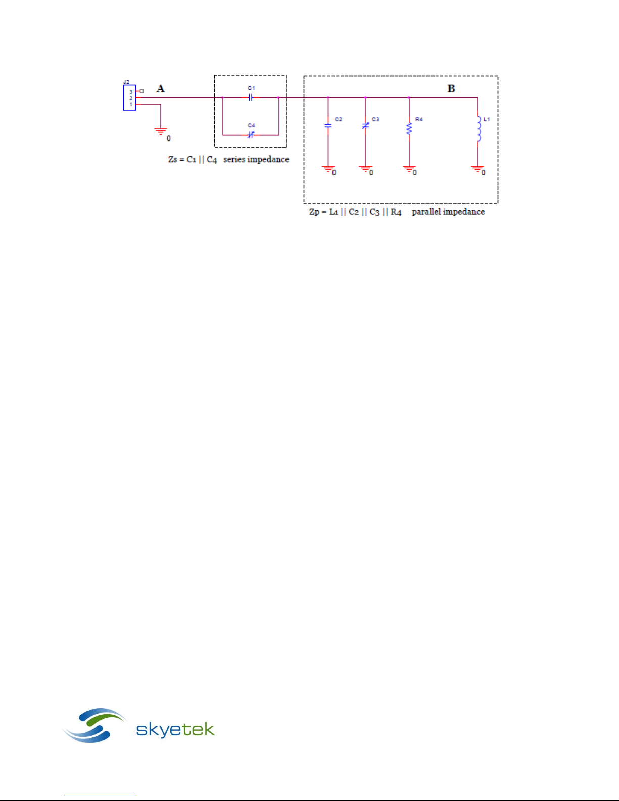
Figure 2-3: The SkyeRead EA1 Circuit
In the figure above, inductor L1 is the physical antenna loop.
Zp forms a resonant circuit tuned at
13.56MHz, so there is an amplification of the ANT signal at B. You can measure and compare the
amplitudes of the sine waves at points A and B as you first adjust C3 to get a maximum amplitude
on the signal at B, and then adjust C4 to further maximize the amplitude of the signal at B.
Autres manuels pour SKYEMODULE M1
1
Table des matières
Manuels Antenne populaires d'autres marques

Alfa Network
Alfa Network APA-L01 Manuel utilisateur

Naval
Naval PR-422CA Manuel utilisateur

Feig Electronic
Feig Electronic ID ISC.ANTH200/200 Series Manuel utilisateur

TERK Technologies
TERK Technologies TV44 Manuel utilisateur

Directive Systems & Engineering
Directive Systems & Engineering DSE2324LYRMK Manuel utilisateur

HP
HP J8999A Manuel utilisateur


CommScope
CommScope CMAX-OMFX-43M-I53 Manuel utilisateur

Ramsey Electronics
Ramsey Electronics DAP25 Manuel utilisateur

COBHAM
COBHAM SAILOR 800 VSAT Manuel d'utilisation et d'entretien

Trango Systems
Trango Systems AD900-9 Manuel utilisateur

Steren
Steren ANT-100 Manuel utilisateur

Proxim
Proxim 5054-PA-23 Manuel utilisateur