Skookum SK-GPS Manuel utilisateur

SK-GPS
Instruction Manual
Rev. 1.10 – August 1, 2014

©Skookum Robotics Ltd.
Ta le of Contents
Safety .......................................................................................................................................................................................................... 1
Box Contents............................................................................................................................................................................................... 2
Getting Started............................................................................................................................................................................................ 3
SK GPS Internal Blue LED States ............................................................................................................................................................. 3
Swash Bump at Init ................................................................................................................................................................................. 3
Mounting the SK GPS.................................................................................................................................................................................. 4
Connecting the SK GPS ............................................................................................................................................................................... 7
Connecting the Superbright EX LED............................................................................................................................................................ 8
Configuring the SK GPS Using the PC Interface .......................................................................................................................................... 9
GPS Responses (Functions)................................................................................................................................................................... 11
Calibrating (Swinging) the Compass ......................................................................................................................................................... 17
Using the SK GPS....................................................................................................................................................................................... 19
Warranty and Technical Support.............................................................................................................................................................. 21

©2014 Skookum Robotics Ltd. 1
Safety
An R/C helicopter is not a toy and can cause serious injury to people or damage to property. Use of this gyro places a flight control
computer (the SK720) between the radio receiver and the servos that position the helicopter’s controls. Loss of control of the
helicopter may result if the SK720 is mistuned or set up incorrectly. See the Warranty and Technical Support section for warranty
information.
WARNING: Stand clear! Always test fly in an area away from spectators and keep yourself at a safe distance when flying the
helicopter, especially after any change in the gyro’s setup or tuning. DO NOT stand closer than 10m (30 feet) from the helicopter
during test hovers or any other flying. Keep bystanders clear of the flight area at all times.
WARNING: Always “safe” the motor before you use the PC setup software or SK LCD terminal to set up or tune your SK 720.
Basic safety practice is to kill the engine on a nitro RC helicopter or disconnect the motor or main battery on an electric RC helicopter
whenever the heli is behind the flight line or is being adjusted in any way.

©2014 Skookum Robotics Ltd. 2
Box Contents
The SK GPS includes:
• The SK GPS unit
• Anti vibration kit for the SK 720
• Tri color super bright External LED
• Two 4 pin connecting cables
• Mounting tape for the SK GPS
Figure 1 - The SK-GPS Module, LED and connecting cables

©2014 Skookum Robotics Ltd. 3
Getting Started
The SK GPS uses the same setup software as the SK 720. However, you will need to upgrade the setup software and SK 720
firmware to the latest versions (3.30 software, 3.30 firmware as of Feb, 2013) in order to set up and use the GPS module.
SK-GPS Internal Blue LED States
There are five (5) LED indicator states for the SK GPS. These states are shown in the table below:
Figure 2 - SK-GPS LED Patterns
LED State Mode
Solid Good satellite lock
Slow Flash Searching for satellite lock
Fast Flash Error
Short Single Blinks Compass swing mode, Yaw
Short Dou le Blinks Compass swing mode, Nose Up
A demonstration of the different LED states can be found on our Youtube channel
(http://www.youtube.com/user/SkookumRobotics)
Swash Bump at Init
Normally, when the SK 720 finishes initializing it will “bump” the swashplate up and down to show it’s ready to fly. If the SK GPS is
connected, the swash bump will not happen until the SK GPS also has a satellite lock.
If your heli is a multicopter, the SK 720 will instead give two very short pulses of all the motors.

©2014 Skookum Robotics Ltd. 4
Mounting the SK-GPS
The SK GPS can be mounting in four different configurations. In all configurations the module’s antenna (the black dome) must
point upwards in order to receive a good signal. It should also have a clear view of as much of the sky as possible, without carbon
fibre or metal covering it or directly beside it. Plastic or thin fibreglass canopies are normally ok.
The GPS module must also be mounted 90° to the helicopter’s frame, aligned with the main shaft, with its back parallel to the tail
boom. As a result, the SK GPS can be mounted label-left, label-right, label-front, and label-aft. The diagram below displays an
example of each mounting position on both a single rotor helicopter.
If you mount your GPS module on your heli’s tail boom, make sure to position it no more than half way to the tail assembly. If you
mount the GPS module away from the helicopter’s centre of gravity, be sure to change the Offset setting in the software. An
explanation of the Offset setting can be found in the Configuring the SK-GPS section.
Figure 3 - SK-GPS Mounting Positions

©2014 Skookum Robotics Ltd. 5
Figure - Antenna Configuration
©2014 Skookum Robotics Ltd. 6
The 3 axis magnetic compass built into the SK GPS is sensitive to some of the magnetic components on helicopters. Specifically, the
SK GPS should be mounted at least:
• 10cm (4”) from ESCs
• 15cm (6”) from motors
• 5cm (2”) from servos
The cable for the GPS should also be at least 3cm (1”) from motor or battery wires, and should be at least 1cm (0.5”) from servo
wiring. It is OK for the GPS wire to cross servo wiring at 90 degrees.
When mounting the GPS unit, it may help to watch the Magnetic Field Strength display on the GPS form in the setup software. Aim
for a mounting location with a field strength under 2. Note that often bolts can be strongly magnetized, so replacing them with
stainless steel bolts may help.
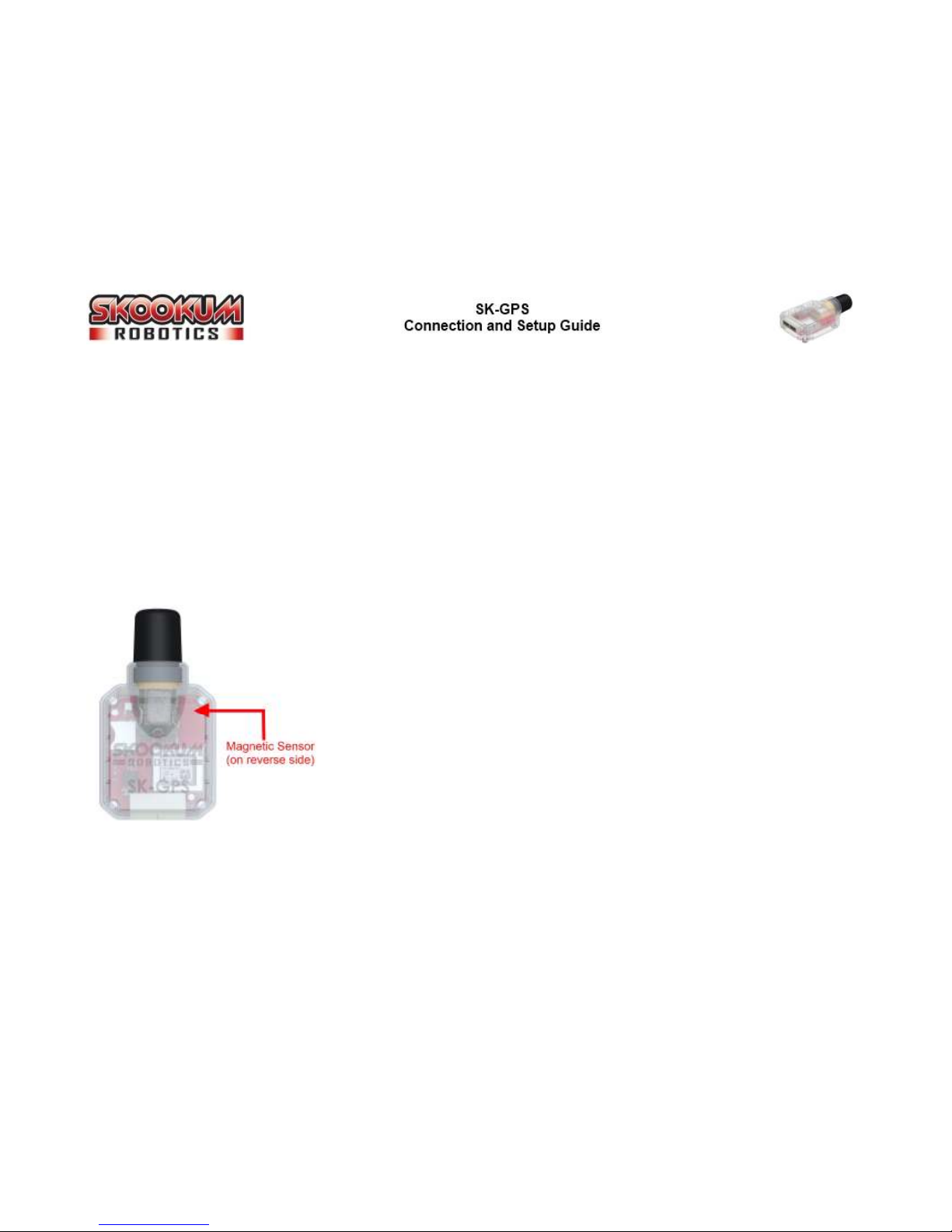
The location of the GPS unit’s magnetic sensor is shown in the image on the left, on the
upper right corner of the unit. The sensor itself is on the underside of the circuit board.
The metal ring included with the GPS cable is a ferrite bead, not a magnet. This ring
reduces high frequency electronic noise. Other tips for reducing EMF and electronic noise
include:
• If cables have to cross, they should cross at 90°
• Don’t run ESC or main battery wires near servo cables, the SK GPS, or its cable
• Don’t run any other wire in parallel with the GPS cable
• Avoid mounting near magnets or bolts (any steel bolt can be considered a magnet)

©2014 Skookum Robotics Ltd. 7
Connecting the SK-GPS
The SK GPS module connects to the SK 720s GPS port using the included 4 pin cable. The second port on the SK GPS module is used
for future Skookum accessories.
Figure 5 - Connecting the SK-GPS to the SK-720
©2014 Skookum Robotics Ltd. 8
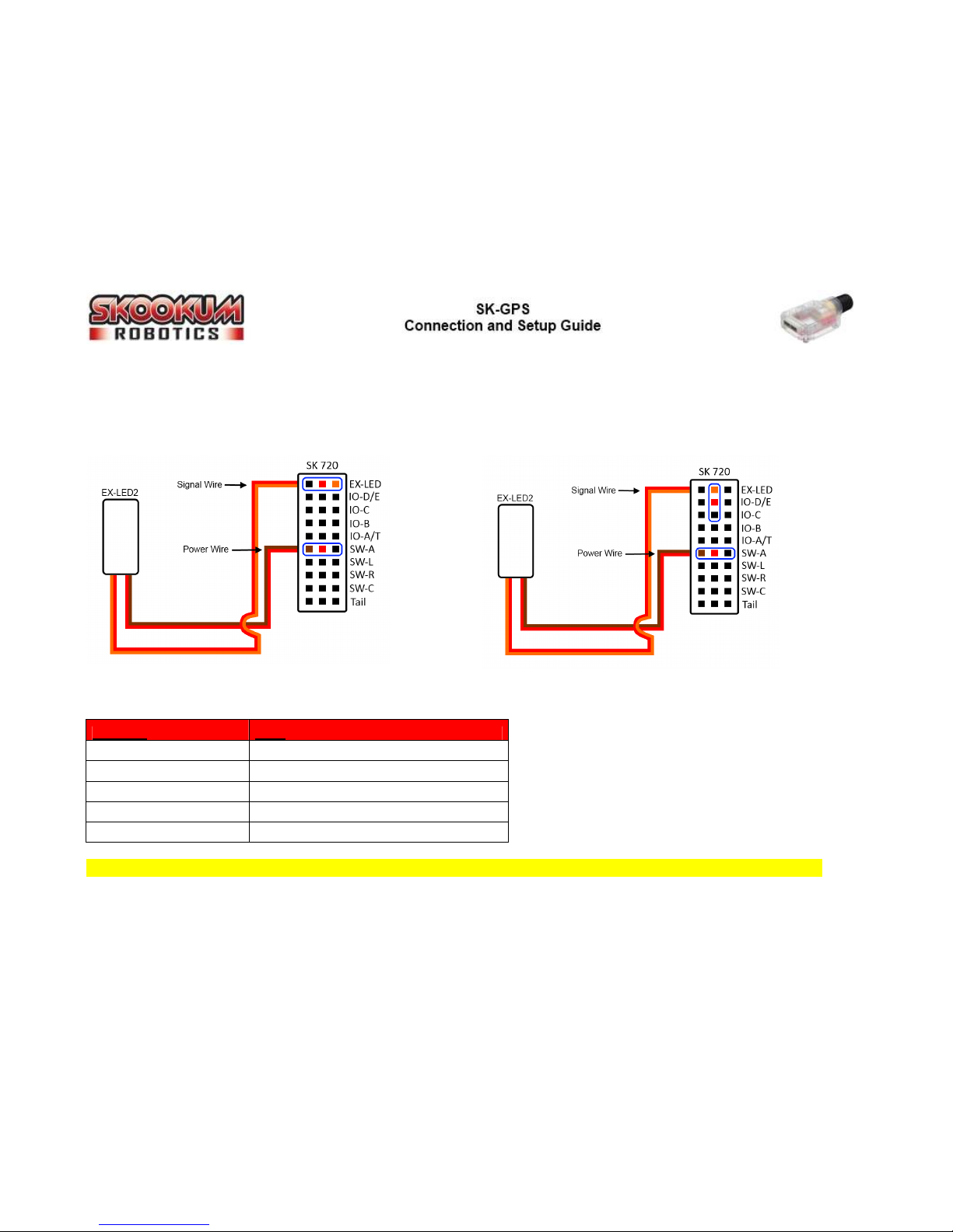
Connecting the Super right EX-LED
The SK GPS comes with a super bright tricolor version of the SK EX LED (Red / Green / Blue). It has one 3 wire jumper that connects
to the SK 720’s EX LED port, and a standard power cable that can be connected to any 5 to 8 volt source.
Figure 6 – Connecting the SK-LED2
All except blue SK 720's with a "Traditional Receiver"
Only blue SK 720’s with a “Traditional Receiver”
Figure 7 – SK-LED2 Patterns
LED State Mode
Solid Red Initializing
Solid Green Ready for normal flight (GPS not availa le)
Solid Blue Ready for GPS assisted flight
Flashing Blue / Green GPS has primary control of Heli
Green with Red flicker Vi ration Alarm
WARNING: DO NOT look directly at the Tricolor EX LED. It is extremely bright and only intended for use while flying the heli.
Table des matières


