SKILTEC DUETTE VERTIGLIDE SIDE STACK DESIGNPOWERVIEW MOTORISATION... Dessin dimensionnel

DUETTE®VERTIGLIDE™
SIDE STACK DESIGN
POWERVIEW®MOTORISATION
PRODUCT INFORMATION MANUAL
SECTION: 9G-B DUETTE®VERTIGLIDE™SIDE STACK DESIGN
POWERVIEW®MOTORISATION

PRODUCT INFORMATION MANUAL
SECTION: 9G-B DUETTE®VERTIGLIDE™SIDE STACK DESIGN
POWERVIEW®MOTORISATION
ISSUE DATE: NOVEMBER 2017 ORIGINATOR: SKILTEC
REPLACES ISSUE DATE: APPROVED BY: D.ALTIPARMAKOVA PAGE 3
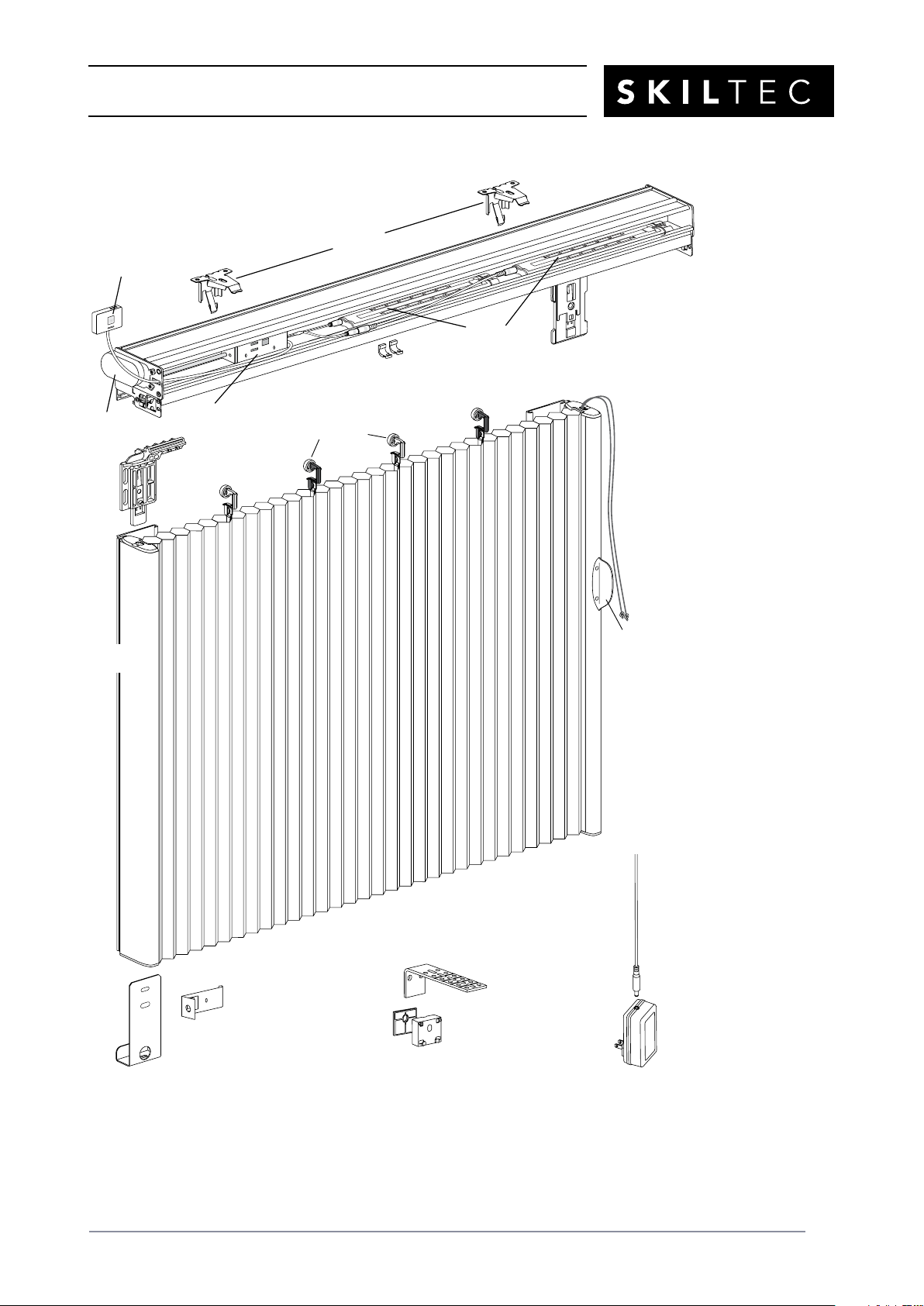
Product View
Left Stack Shown
Stationary
Rail
Bracket
Tension
Cord
Handle
Stationary Rail
Bottom Bracket
*Located inside headrail
Inside
Mount
Adaptor
Moving
Rail
Fabric Carriers
Extension
Bracket
Optional Outside Mount Hardware:
3mm Shim 13mm Spacer
Block
Stationary
Rail
Extension
Cable
DC Power Supply
(Optional)
Headrail
Gearbox
Cord
Tensioners*
Battery
Wands
Moving
Rail
Bracket*
Manual
Control Button
Motor
Installation
Brackets
PRODUCT INFORMATION MANUAL
SECTION: 9G-B DUETTE®VERTIGLIDE™SIDE STACK DESIGN
POWERVIEW®MOTORISATION
ISSUE DATE: NOVEMBER 2017 ORIGINATOR: SKILTEC
REPLACES ISSUE DATE: APPROVED BY: D.ALTIPARMAKOVA PAGE 4
Thank you for purchasing Luxaflex®Duette®Vertiglide™honeycomb shades. With proper
installation, operation, and care, your new shades will provide years of beauty and performance.
To get started, unpack the shade and remove all foam/
packaging materials. Check that all parts shown on
the packing list are included with the order.
Please thoroughly review this instruction booklet before
beginning the installation.
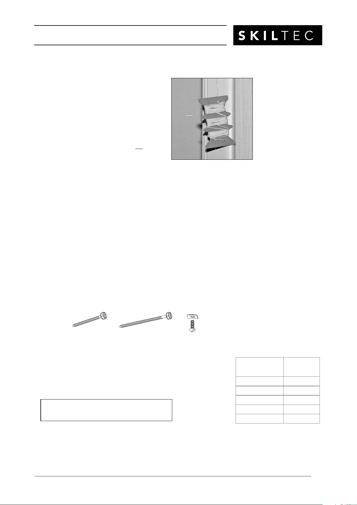
IMPORTANT: Cords are wrapped around a
cord organizer located approximately 152mm
from the top of the moving rail. Please do not
unwrap the cords until instructed to do so.
Tools and Fasteners Needed
■Flat blade and magnetic-tipped Phillips screwdrivers
■Level (laser level is recommended)
■Measuring tape and pencil
■Power drill, 3mm
drill bit, and 6mm hex driver
■Scissors
In addition, you will need fasteners designed to work with your specific mounting surface(s).
■#6 Hex Head Screws (Provided). Two 38mm screws are provided per installation bracket.
■Longer #6 Hex Head Screws (Not Provided). If using spacer blocks, use #6 screws long
enough for a secure attachment.
■Speed Nuts and Screws (Provided). Extension brackets come with speed nuts and screws.
■Drywall Anchors (Not Provided). Use drywall anchors when mounting into drywall.
Installation Brackets Required
■The number of installation brackets required varies with headrail width, as
shown in the table.
Speed Nut
and Screw
(Two Provided with
Each Extension Bracket)
#6 x 38mm
Hex Head Screw
(Provided)
Longer #6 Hex Head Screw
for Use with Spacer Blocks
(Not Provided)
Do Not
Unwrap
Cords
NOTE: Two installers are recommended for shades
over 2130mm wide.
Shade
Width
Brackets
Required
310mm – 788mm 2
789mm – 1675mm 3
1676mm – 2440mm 4
2441mm – 3531mm 5
3532mm – 4270mm 6
PRODUCT INFORMATION MANUAL
SECTION: 9G-B DUETTE®VERTIGLIDE™SIDE STACK DESIGN
POWERVIEW®MOTORISATION
ISSUE DATE: NOVEMBER 2017 ORIGINATOR: SKILTEC
REPLACES ISSUE DATE: APPROVED BY: D.ALTIPARMAKOVA PAGE 5
Installation Overview
Installation of Vertiglide™shades varies based on the shade mounting type and stacking design
selected.
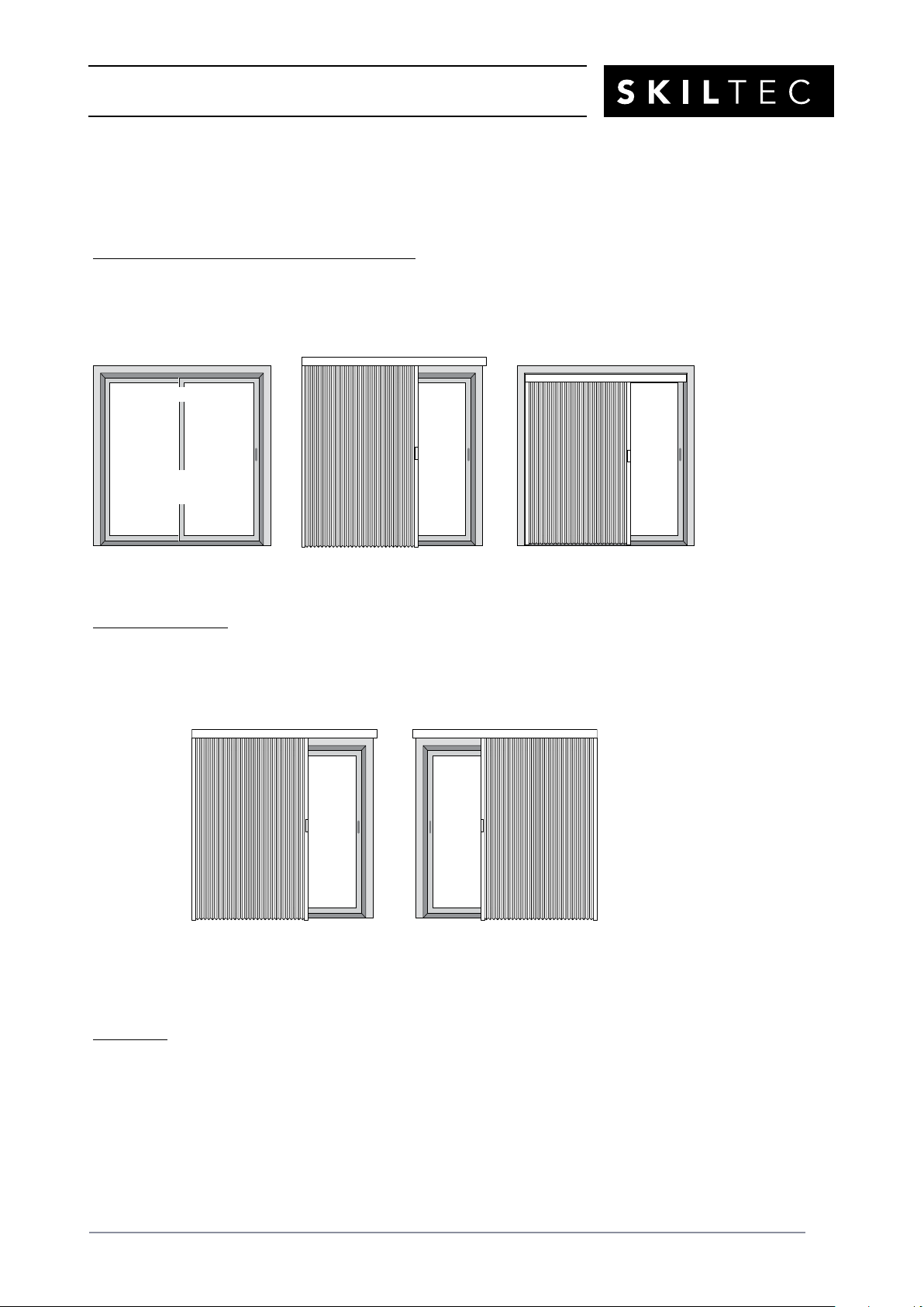
Mounting Types and Window Terminology
■Review the mounting types and basic window terminology illustrated below. Determine if
your shade is an outside mount or inside mount. For ceiling mount applications, refer to the
inside mount instructions.
Stacking Designs
■Determine which Vertiglide stacking design you are installing: left stack or right stack.
■If a sliding glass door opens from the right side, a left stack design is best. If the door opens
from the left side, a right stack design is best.
NOTE: A left stack design is shown throughout these instructions. Procedures for a right stack
design are the same but at opposite sides of the fabric stack and headrail.
Next Step
■Refer to the page below based on your shade mounting type:
➤Face Mount — Page <?>
➤Reveal/Ceiling Mount — Page 9
Molding
Floor
Jamb Jamb
Head Jamb
Outside Mount
Shade mounts outside
door or window opening.
Inside Mount
Shade fits within door
or window opening.
Window or
Patio/Sliding Door
Left Stack Right Stack

PRODUCT INFORMATION MANUAL
SECTION: 9G-B DUETTE®VERTIGLIDE™SIDE STACK DESIGN
POWERVIEW®MOTORISATION
ISSUE DATE: NOVEMBER 2017 ORIGINATOR: SKILTEC
REPLACES ISSUE DATE: APPROVED BY: D.ALTIPARMAKOVA PAGE 6
Face Mount
Mount the Installation Brackets
■Center the headrail over the window opening at the desired height. Use a pencil to mark
each end of the headrail. (On the stacking side, the end of the white gearbox counts as the
end of the headrail.)
➤Alternatively, measure the width of the headrail and use that width to mark the headrail
end points.
■Mark end bracket locations 200mm in from each end of the headrail.
➤Mark the locations of any additional brackets, spaced evenly between the two end
brackets. Mount into wood whenever possible.
■Determine where to place the top of the installationbrackets.
➤Add the desired floor clearance to the ordered
height of the shade. The ordered height can be
found on the packaging label. A minimum of 13mm
floor clearance is recommended.
➤Measure the total distance up from the floor. This is
where to place the top of the installation brackets.
➤A minimum flat vertical surface of 32mm is required
to mount the brackets.
CAUTION: The rear of the brackets must be flush
against a flat mounting surface. Do not mount
brackets oncurved molding.
■Center the brackets on your marks and mark the screw holes.
➤When using extension brackets, mark two screw holes
per bracket.
Headrail End Marks
Window/Door Opening
8" 8"
Space Evenly Space Evenly
Top of
Bracket
FloorClearance
Ordered
Shade
Height
PRODUCT INFORMATION MANUAL
SECTION: 9G-B DUETTE®VERTIGLIDE™SIDE STACK DESIGN
POWERVIEW®MOTORISATION
ISSUE DATE: NOVEMBER 2017 ORIGINATOR: SKILTEC
REPLACES ISSUE DATE: APPROVED BY: D.ALTIPARMAKOVA PAGE 7
■Drill the screw holes using a 3mm drill bit.
CAUTION: Use drywall anchors when mounting into drywall. Use the drill bit size
recommended by the manufacturer.
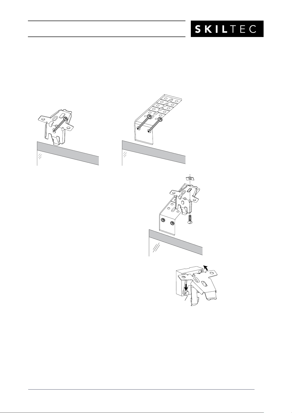
■Attach the installation or extension brackets using the screws provided.
IMPORTANT: The front edges of the brackets must be level and aligned to each other.
■If using extension brackets, attach an installation bracket to
the underside of each extension bracket using theprovided
screws and speed nuts.
■If using spacer blocks, first attach the installation bracket to the
13mm spacer block before stacking additional spacer blocks or
shims together.
➤Insert the legs of the installation bracket into the tabs on the
spacer block.
➤Then rotate the installation bracket back.
➤Use a maximum of three spacer blocks (38mm) per installationbracket.
IMPORTANT: For the 38mm pleat size, a minimum 6mm rear clearance is recommended.
Tab

PRODUCT INFORMATION MANUAL
SECTION: 9G-B DUETTE®VERTIGLIDE™SIDE STACK DESIGN
POWERVIEW®MOTORISATION
ISSUE DATE: NOVEMBER 2017 ORIGINATOR: SKILTEC
REPLACES ISSUE DATE: APPROVED BY: D.ALTIPARMAKOVA PAGE 8
■Attach the spacer blocks and installation brackets
with #6hex head mounting screws long enough for
asecure installation. (See chart below.) Longer screws
are not provided.
➤The top of the spacer blocks should be at the
desired shade height.
➤The front edges of the installation brackets must
be level and aligned to each other.
CAUTION: Use drywall anchors when mounting
into drywall.
CAUTION: The rear of the spacer blocks must be flush against a flat surface. Do not mount
spacer blocks and installation brackets oncurved molding.
76mm (Not provided; up to 38mm of spacer blocks/shims)
64mm (Not provided; up to 29mm of spacer blocks/shims)
Never use more than 38mm of spacer blocks/shims!
IMPORTANT: The provided 38mm screws can only
be used with a maximum of one 3mm shim. You will
need to supply longer screws if additional
clearance is required.
A minimum 32mm length of screw threads must
extend beyond the last spacer block or shim.
Use appropriate wall anchors when mounting
into drywall.
51mm (Not provided; up to 16mm of spacer blocks/shims)
32mm Minimum
Shim
Maximum of One
Shim with Provided
38mm Screws
Longer Screw
(Not Provided)
Maximum
38mm
PRODUCT INFORMATION MANUAL
SECTION: 9G-B DUETTE®VERTIGLIDE™SIDE STACK DESIGN
POWERVIEW®MOTORISATION
ISSUE DATE: NOVEMBER 2017 ORIGINATOR: SKILTEC
REPLACES ISSUE DATE: APPROVED BY: D.ALTIPARMAKOVA PAGE 9
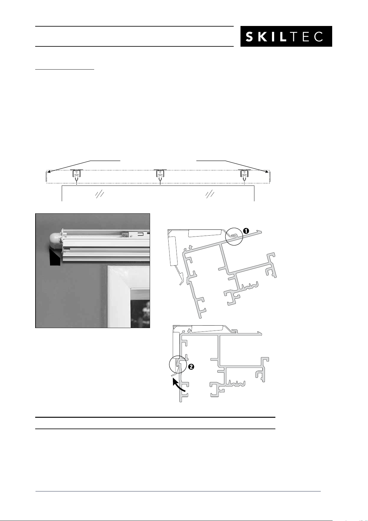
Mount the Headrail
■Mount the headrail into the installation brackets. Do not remove any components from the
headrail. Both end plates should remain attached to the ends of the headrail.
➤Carefully align the headrail with the end marks on the mounting surface. Headrail
position cannot easily be adjusted after the headrail is mounted. (Remember that the
end of the white gearbox is the end of the headrail on the stacking side.)
➤Place the front groove on the headrail onto the front lip of the installation brackets.
➤Rotate the rear of the headrail up and push back until the headrail snaps in place.
Proceed to “Install the Fabric Stack” on page 11.
Align Headrail with End Marks
Align End of
Gearbox with
End Mark
Snap in
Place
Place Groove onto
Front of Bracket
PRODUCT INFORMATION MANUAL
SECTION: 9G-B DUETTE®VERTIGLIDE™SIDE STACK DESIGN
POWERVIEW®MOTORISATION
ISSUE DATE: NOVEMBER 2017 ORIGINATOR: SKILTEC
REPLACES ISSUE DATE: APPROVED BY: D.ALTIPARMAKOVA PAGE 10
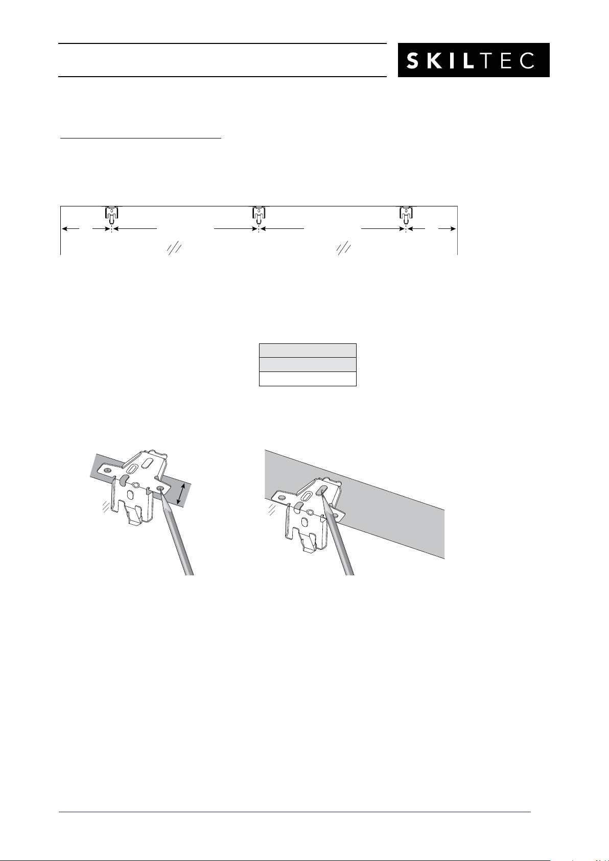
Reveal/Ceiling Mount
Mount the Installation Brackets
■Mark 200mm in from each jamb. This marks the center points of the two end brackets.
➤Mark the locations of any additional brackets, spaced evenly between the two end
brackets.
■Center the brackets on your marks and mark the screw holes.
➤The minimum casement depth for mounting the installation brackets is 13mm. Mark
both of the winged screw holes with shallow mounting depths.
➤The minimum casement depth for
a fully recessed mount varies with
valance type and fabric pleat size, as
shown in the table. Mark the center
screw hole when depth permits.
IMPORTANT: For the 38mm pleat size, a minimum 6mm rear clearance is
recommended.
■Drill the screw holes using a 3mm drill bit.
CAUTION: Use drywall anchors when mounting into drywall. Use the drill bit size
recommended by the manufacturer.
Window/Door Opening
200mm Space Evenly
Jamb Jamb
Space Evenly 200mm
Minimum
13mm Use Center Hole
When Depth Permits
Fully Recessed Depth
20mm Pleat
98mm
Table des matières
Autres manuels SKILTEC Mobilier d'intérieur


