5. OPERATION
5.1 Control logic
The NEX Series® CE12 Duplex control panel operates with 2~4 float switches. Multiple control pro-
gram available through DIP switch. Through setting up of pump rated current on the current setting
switch, the panel will provide the overload protection to the motors.
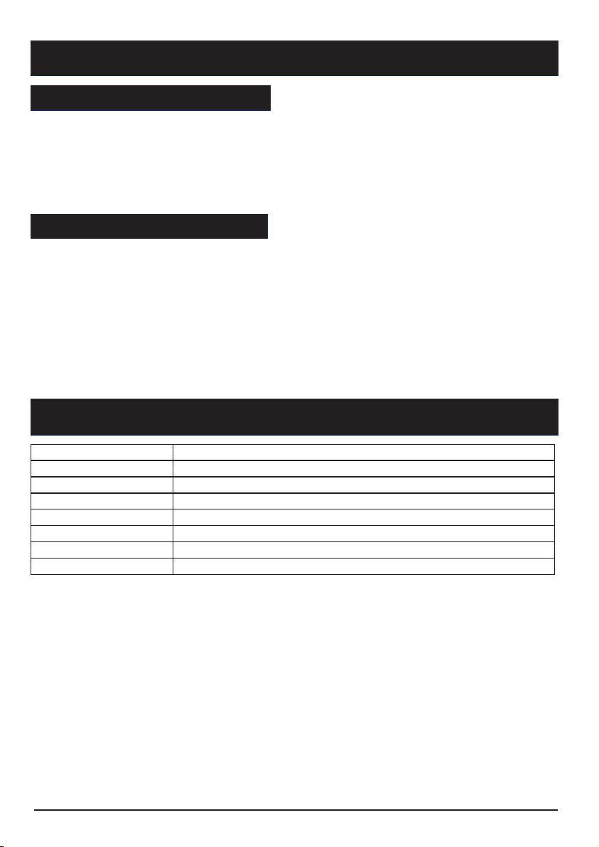
Hand-Off-Auto (HOA) Switches
In HAND mode, the pump will turn ON.
In OFF mode, the pump will turn OFF.
In AUTO mode, commands from the float switches turn each pump ON and OFF.
DIP Switch
Current Setting Switch
Turn the current setting switch, make the arrow point to the rated current of the pump. The overload
protection function will be activated.
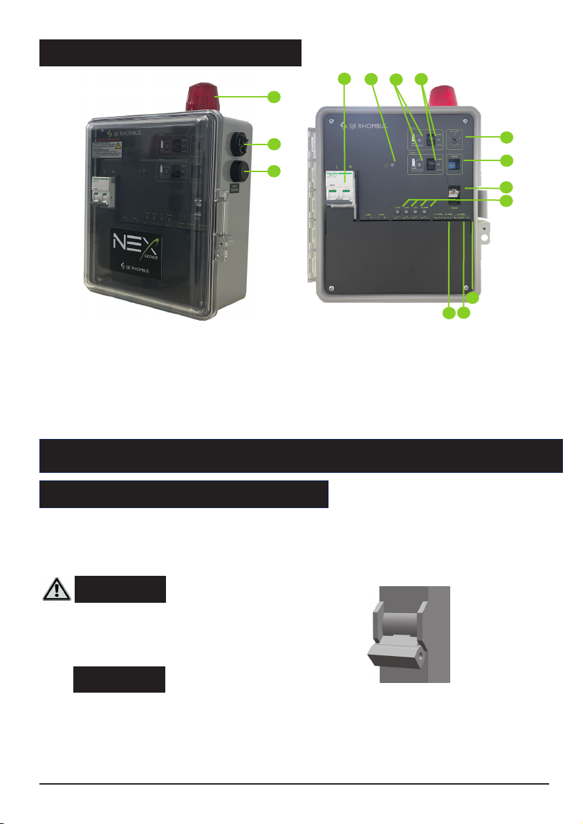
5.2 Operation components
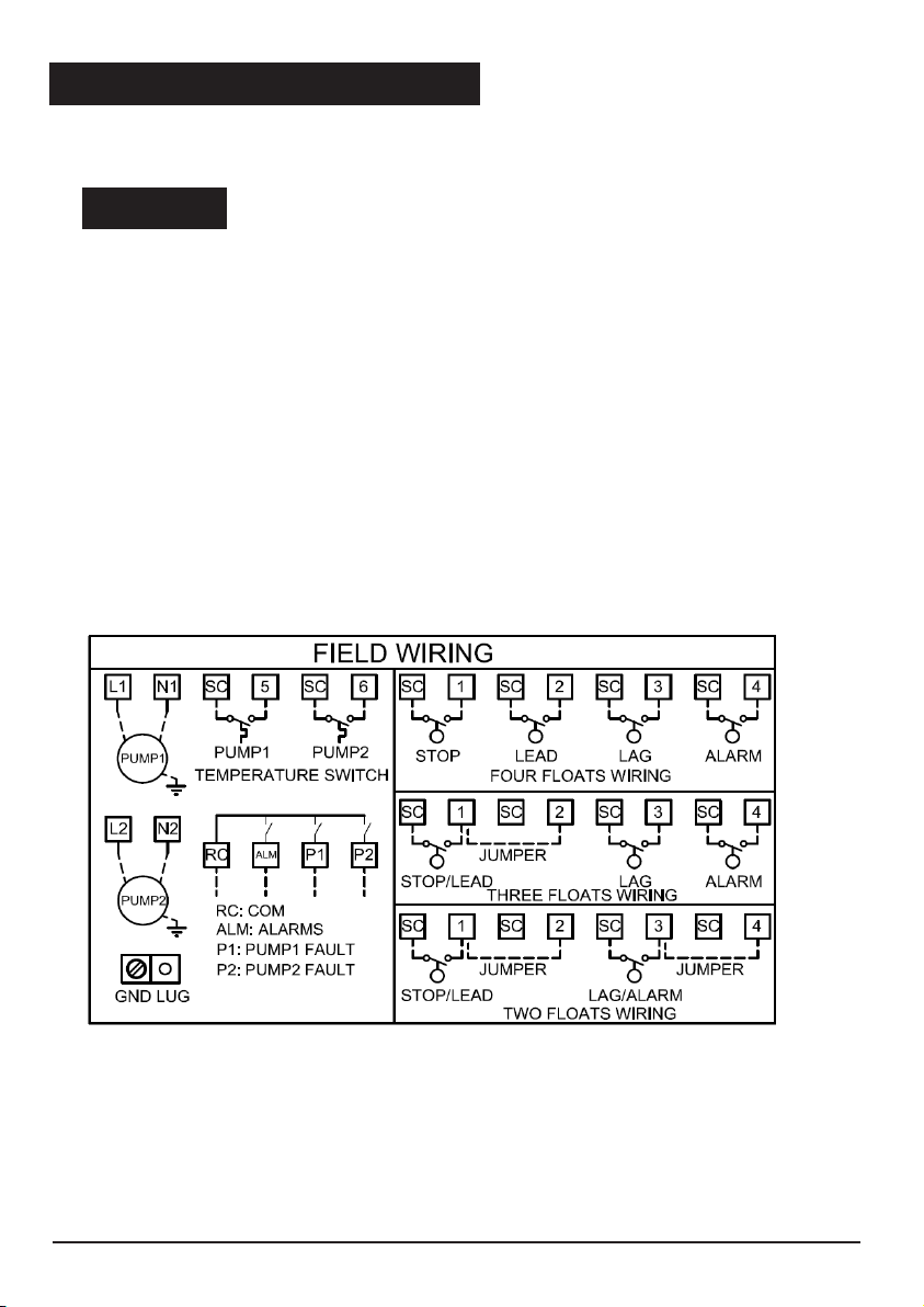
2 float switches:
When the liquid level rises, the STOP/LEAD float close , the Lead pump will turn ON. If the liquid level
keep rising, the LAG/ALARM float close, the Lag pump will turn on, and the alarm will be activated.
When the liquid level decrease, the LAG/ALARM float open, the alarm will be stopped. Both two pumps
will remain ON until the STOP/LEAD float return to the OFF position. The two pumps will be alternatively
start by STOP/LEAD float.
3 float switches:
When the liquid level rises, the STOP/LEAD float close, the Lead pump will turn ON. If the liquid level
keep rising, the LAG float close, the Lag pump will turn on. Both two pumps will remain ON until the
STOP/LEAD float return to the OFF position. If the liquid level rises to reach the ALARM float, the
alarm will be activated. The two pumps will be alternatively start by STOP/LEAD float.
4 float switches:
When the liquid level rises and closes the STOP float, the panel remains inactive until the LEAD float
closes. At this point the LEAD pump will turn ON. The pump will remain ON until both the STOP and
LEAD floats return to their OFF positions. If the liquid level rises beyond both the “Stop” and LEAD floats
to reach the LAG float, the lag pump will turn ON. Both pumps will remain ON until the STOP, LEAD,
and LAG floats return to their OFF positions. If the liquid level rises to reach the ALARM float, the alarm
will be activated.
Position Function ON OFF
1Overload protection reset method Auto Manual
2PSE protection Enable Disable
3Weekly exerciser Enable Disable
4Float connection 2 or 3 floats 4 floats
7
Circuit Breakers
Each pump circuit has a thermal-magnetic circuit breaker that provides pump disconnect
and branch circuit protection.
Alarm Horn/Beacon
When an alarm condition occurs, the red light and horn will be activated. Press the TEST/SILENCE
button, the horn will be silenced. but the red light remains ON until the alarm condition release. When
the alarm condition is cleared, the alarm horn/beacon will be auto reset.
When no alarm condition occurs, press “TEST/SILENCE“ button to test the alarm horn and light.
Weekly Exerciser
Both pumps will be running automatically once a week for 10 seconds to prevent the clog in case of
long time out of operation.
6. PANEL PROTECTIONS AND ALARMS
6.1 Pump overload protection/alarm
This alarm appears in the event of a current overload on the pumps. The overload protection is conform
to IEC class 10 curve. The pump overload protection can be manually or auto reset. For each pump the
current overload alarm allows 3 auto-reset attempts. After three attempts, the panel no longer makes
auto-resets, unless the problem is resolved, then the system can be manual reset. To solve this problem,
check the pumps, the wiring, and ensure the rated current of the pumps is set correctly. This error may
be generated by a blocked pump. (Please refer to Figure 4)
6.2 Pump over-temperature protection/alarm
The panel has terminal blocks that can be connected with pump’s thermo switch. In normal status, the
thermo switch is closed. When pump’s internal termperature increase that the thermo switch open, the
panel will send over-temperature alarm notice. The pump will not start until the thermo switch closed.
When the pump internal temperature decrease that the themo switch closed, the pump will restart to
work. The pump over-temperature protection can only be reset automatically. (Please refer to Figure 4)
The PSE monitoring function is the latest in Machine Learning Technology developed specifically for
wastewater pumping applications. The proprietary algorithm continuously monitors the tank fill time
and discharge times and “learns” what is normal. Should the pump performance drop due to clogging,
impeller damage, or changes in head conditions, the PSE function will trigger an alarm. This intelligent
solution is not affected by flow variations into the tank and can detect pump Dry Run conditions. The
PSE function can be enabled or disabled via the DIP switch on the control panel. The installer can turn
the PSE function ON as soon as the system is up and running and system is operating normally. The
controller is now able to detect pump system anomalies that are otherwise un-detectable by traditional
control panels. Early detection is key to a reliable pumping system and will save time and money by
addressing problems before failure. (Please refer to Figure 4)
6.4 Pump fault inspection (Duplex panel)
The panel provides pump fault inspection . When one pump start to operate as the lead pump, the lag
pump always operate together, if this situation occur three times consecutively, the system will judge that
the lead pump is fail. This pump fault alarm can only be reset manually when the pump fault recovered.
And this function can only be applied in duplex panel system. (Please refer to Figure 4)
8