Siyata VK7 Manuel utilisateur

Quick Installation Guide
ENGLISH | FRANÇAIS | ESPAÑOL
1-888-316-3747 www.siyata7.com

2
EN Installation Guide 5
FR Guide d'installation rapide 17
ES Guía de Instalación Rápida 30
Device Layout / Disposition de l’appareil /
Disposición del dispositivo
3
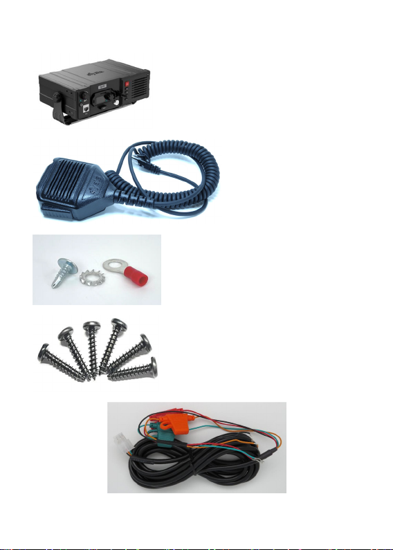
VK7 Parts / Pièces du VK7 / Partes del VK7
VK7 Device /
Appareil VK7 /
Dispositivo VK7
Wired RSM /
RSM filaire /
RSM cableado
Installation Kit /
Kit d’installation /
Kit de instalación
Power cord and fuses / Câble électrique et fusibles /
Cable de alimentación y fusibles
4
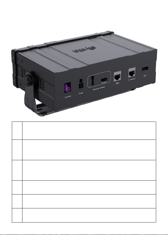
VK7 Rear View / Vue arrière du VK7 /
Vista posterior del VK7
1
External RF Rod Antenna Connection
Connexion d'antenne tige RF externe
Conexión a antena de varilla externa para RF
2
Power Cable Connection
Connexion de câble d’alimentation
Conexión del cable de alimentación
3
20 External Speaker Connection
Connexion de haut-parleur externe
Conexión a altavoz externo de 20 W
4Wired RSM Connection
Connexion du RSM filaire / Conexión RSM cableada
5Private Handset Connection / Connexion du combiné privé
Conexión de microteléfono con privacidad
6USB OTG Connection / Connexion USB OTG
Conexión USB OTG

5
English
ENGLISH
Table of contents
Preplanned Accessory Positioning ....................................... 6
Installing the Bracket and Device ......................................... 8
Installing the Speaker ........................................................... 9
Installing the Electrical Connections .................................. 10
Installing the RF Rod Antenna ............................................ 12
Troubleshooting ................................................................. 13
Optional Accessories ......................................................... 16

6
English
Preplanned Accessory Positioning
Positioning of all accessories must be planned in advance before
installation begins.
Ensure that no wire braids go through locations where Device
accessories are to be installed.
Ensure that any parts of the Device will not interfere with the
vehicle or its accessories’ operation
Plan Device and mounting bracket Positions
Note!
The best way to determine the Device’s position to
the customer’s full satisfaction is to locate it when
the customer is beside you and obtain his/her
approval.
Please ensure the Device’s location does not interfere
with the vehicle or its accessories operation: it should not
interfere with opening the glove compartment or ashtray,
should not prevent access to the lighter, moving the gear
stick, operating the hand brake etc.
If the Device is installed near the car windshield/dash board,
ensure that it does not interfere with the visual field.
Warning!
Do not install the Device in front of the vehicle’s air
bag. This restriction must be adhered to, as in the
case of an emergency the air bag blows up and can
fail to work properly.
Ensure the surface on which this Device is installed is
sufficiently strong to carry the weight and pressure which
would be exerted on it.

7
English
When selecting the Device’s location, please ensure the
control cable connected to it does not interfere with the
vehicle or its accessories’ operation.
Ensure it is safe and convenient to operate the Device from
the driver’s seat.
Ensure the Device would be protected from direct sunlight
and humidity (air conditioner openings).
Ensure the Device would be protected from mechanical
damage by the car’s accessories.
Plan the Wired RSM Position
For performance and user convienence, Install the device’s
Wired RSM using the bracket provided in kit by mounting it
on one of the VK7 side panels or on the Vehicle dash board in
a convenient location.
It is recommended to install the Wired RSM away from the
vehicle’s window and from external sources of noise.
Plan the External Speaker’s Position
(Optional accessory)
Note!
Do not hide the speaker inside the dash board.
If you cover it, sound quality will be lowered.
Locate the speaker at the right side of the main console, at
the front of the console, in a location where it would not
bother the driver or passengers but would sound best.

8
English
Installing the Bracket and Device
1. Disassemble the Bracket joint from its two base sided knob
units.
2. Install the Bracket Kit base unit using the 6 philips screws
provided with this kit.
Note!
Only use the original screws provided with this kit.
3. Put the Device to the Bracket Kit, adjust the angles. Use the
sided knob units in order adjust the Device
Device and Bracket Kit

9
English
Installing the Speaker (Optional accessory)
Where to Locate the Speaker (Reminder)
Note!
Do not hide the speaker inside the dash board.
If you cover it, sound quality will be lowered.
Locate the speaker at the
right side of the main console,
at the front of the console,
in a location where it would
not bother the driver or
passengers but would sound
best.
Installing the Speaker
1. Install the speaker at the right side
of the main console, at the front of
the console.
2. Disassemble the screws connecting
the speaker to the hanger.
3. Install the hanger using the 2 tin
screws.
4. Direct the speaker cable behind the mat located at the
bottom of the car.
5. Ensure the cable does not interfere with the vehicle or its
accessories’ operation.
6. Ensure the speaker cable is not exposed to damage by the
passengers.

10
English
Installing the Electrical Connections
The electrical cable is provided separately from the control
cable. Before installation begins, connect the four leads (which
include the 3A fuses) using a red or blue crimp sleeve as
appropriate.
Warning!
Please note sharp edges or moving parts which may
damage the wires.
The value for the fuses provided with the kits must
not be changed.
The kit is appropriate only for a 12V/24V vehicle.
In case of converting any other kit model into this kit,
please change the power cable.
The electrical cables should be directed as follows:
So as not to disturb the driver or passengers.
So as not to pass near the car’s sharp or moving parts.
Note!
The external voltage connection is located under the
dash board or close to the fuse box (depending on
the car model).
In new vehicles a cellular Device connection can be
found near the fuse box. See the car’s user’s manual
under Info.
Only use the kit’s original fuses (3A).
Table des matières
Langues :


