Sitron CF12 AC Manuel utilisateur

Contents
03
Introduction . . . . . . . . . . . . . . . . . . . . . . . . . . . . . . . . . . . . . . . . . . . . . . . . . 4
Models & Dimensions . . . . . . . . . . . . . . . . . . . . . . . . . . . . . . . . . . . . . . . . . 5
Wiring Diagram . . . . . . . . . . . . . . . . . . . . . . . . . . . . . . . . . . . . . . . . . . . . . . 6
CF12 Relay Status Guide . . . . . . . . . . . . . . . . . . . . . . . . . . . . . . . . . . . . . 10
Pre-Installation. . . . . . . . . . . . . . . . . . . . . . . . . . . . . . . . . . . . . . . . . . . . . . 11
Installation . . . . . . . . . . . . . . . . . . . . . . . . . . . . . . . . . . . . . . . . . . . . . . . . . 12
Calibration . . . . . . . . . . . . . . . . . . . . . . . . . . . . . . . . . . . . . . . . . . . . . . . . . 14
Handling . . . . . . . . . . . . . . . . . . . . . . . . . . . . . . . . . . . . . . . . . . . . . . . . . . 15
Technical Specifications . . . . . . . . . . . . . . . . . . . . . . . . . . . . . . . . . . . . . . 16
Ordering Information . . . . . . . . . . . . . . . . . . . . . . . . . . . . . . . . . . . . . . . . . 20
Trouble Shooting . . . . . . . . . . . . . . . . . . . . . . . . . . . . . . . . . . . . . . . . . . . . 21
Terms & Conditions . . . . . . . . . . . . . . . . . . . . . . . . . . . . . . . . . . . . . . . . . 22
04
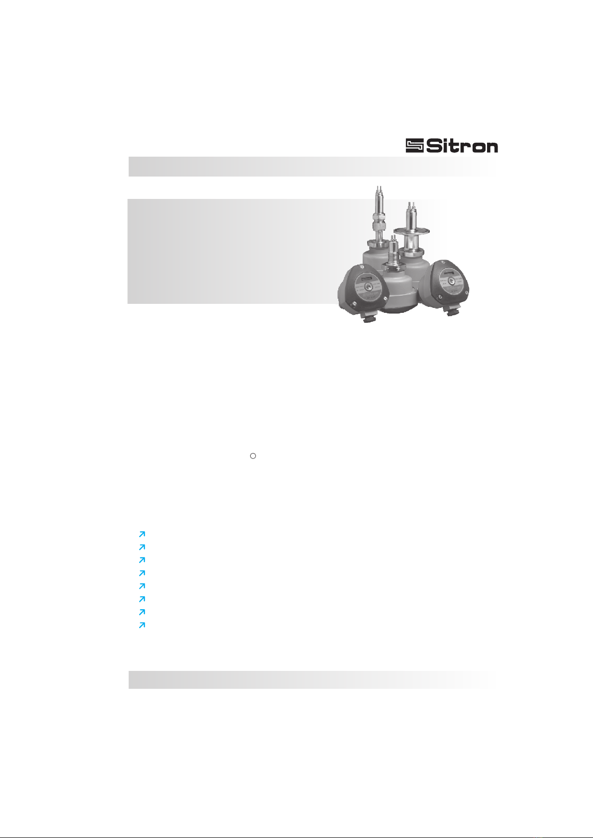
Introduction
CF12 AC / CF12 DC
Thermal Dispersion Flow
Switch Monitor
The CF12 series of thermal flow switches is designed to monitor flow status of liquids and
gases and can also be used to detect level.
Achain of 8 LED's gives the user a visual indication of the flow status of the switch. There are
two red LEDs that indicate whether or not the unit has detected flow, a yellow LED to indicate
the set point (for increasing or decreasing flows) and 5 green LEDs that indicate the amount
of flow beyond the set point of the unit. The CF12 also includes a di-chromatic (red/green)
LED which shows the switch point status of the unit.
The sensing element and connection of the CF12 are made with 316 S.S. and can be coated
when necessary . The enclosure is offered in either glass filled nylon or aluminium.
All models can be ordered with a great variety of threaded, flange, or sanitary procces
connections as well as Hallar or epoxy coating for aggressive mediums.
For Hallar coating we recommend that the switches are made with flanged connections or a
minimum of 1” threaded connection.
Simple to install.
Excellent low flow sensitivity.
Available in X-proof version.
No moving parts-maintenance free reliabity.
Can be coated for aggressive mediums.
Maximum working pressure of 1450 PSI (100 bar).
Fast response time for flow or level (Adjustable from 1-10 seconds).
Avaliable in threaded, sanitary and adjustable insertion length connections.
R
Features
05
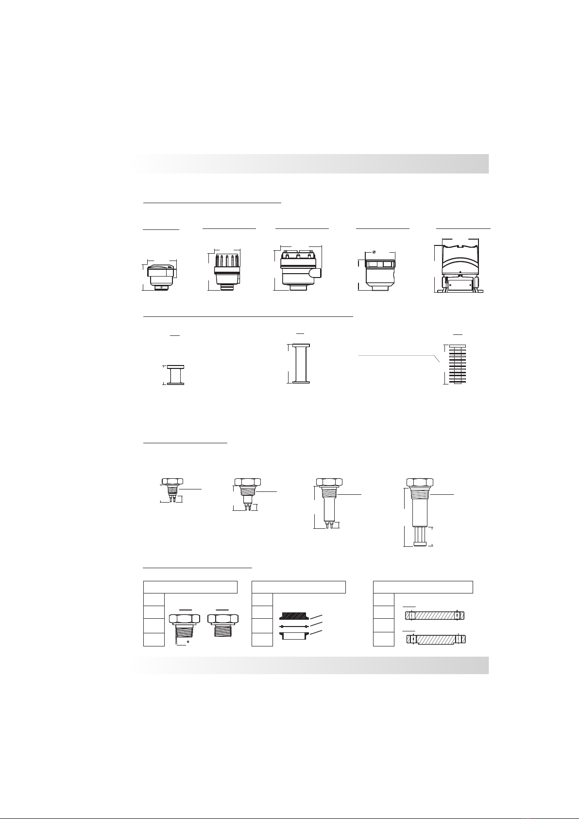
Models and Dimensions
Threaded Connections
MT - Medium (up to 120ºC)
AT - High temperature (up to 150ºC)
HT - Ultra High temperature (up to 250ºC)
temperature
Other insertion lengths are available upon request
3/4”
1 ½”
1 ½” 1 ½”
2 ½” 2 ½”
1”
½”
2” 2”
1” 1”
1,75
Tri-Clamp Connection Flange Connections
Mounting Options for CF12
Extended Necks for Higher Temperatures
Process Connections
TC Connection
ANSI 150#
ANSI 300#
Rubber Seal
Process Connection
NPT BSP FF
RF
100mm
100mm
100mm
50mm
45mm
35mm
50mm
75mm
12mm
12mm
12mm
3/4” NPT
1” NPT 1” NPT
½” NPT
CF12 w/ insertion
length of 35mm
CF12 w/ insertion
length of 50mm
CF12 w/ insertion
length of 75mm
CF12 for Ultra High temperature w/
minimum insertion length of 100mm
Ultra High temp. neck w/
heat dissipating rings
HT
AT
MT
Insertion Length
Nylon-N1 Aluminum-G2 Aluminum-G3
Aluminum-G1
126mm
130mm
130mm
89mm
76mm
89mm
82mm
80mm
161mm
127mm
Aluminum-GX
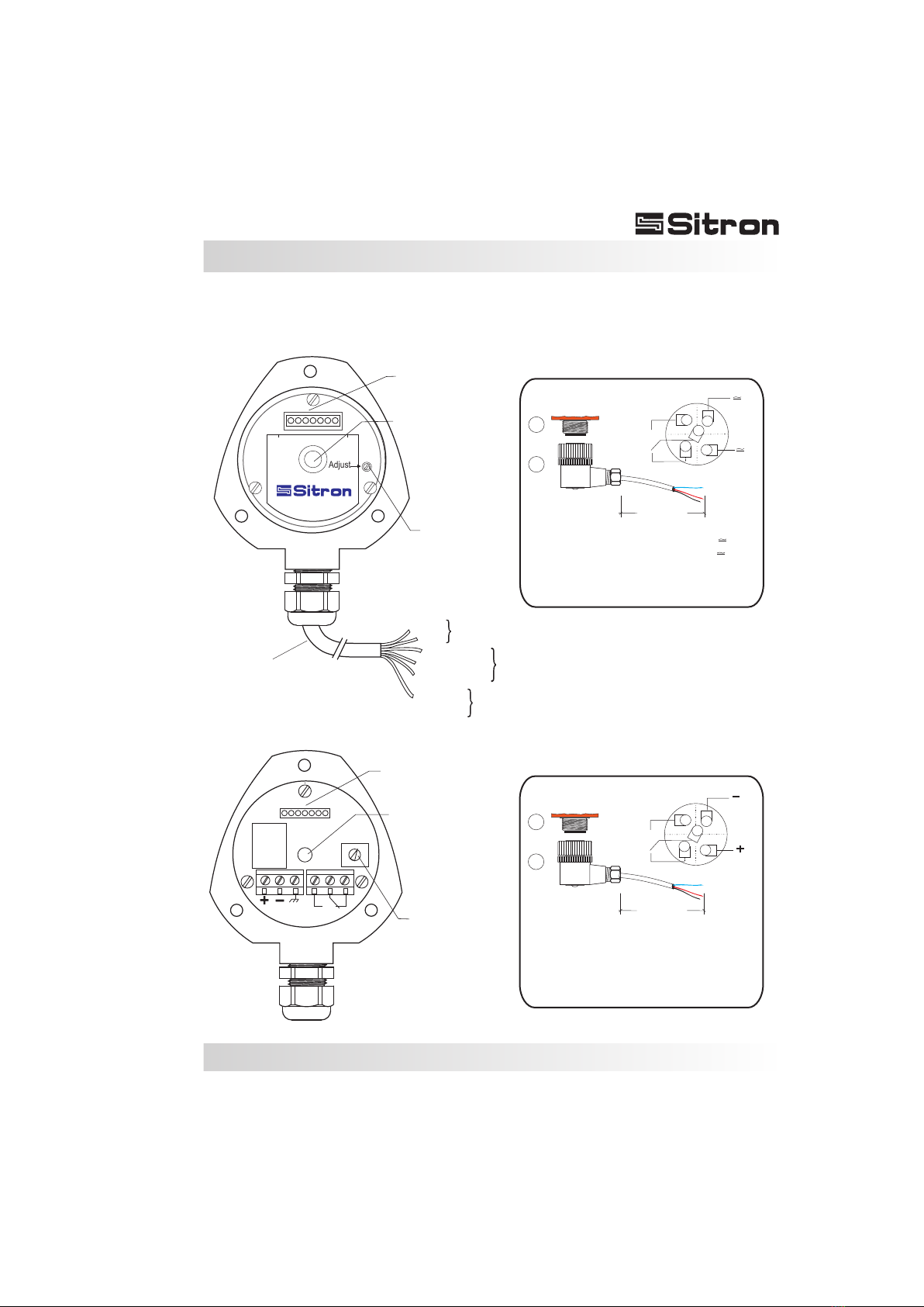
06
Wiring Diagram
Standard Connection w/
2 meters of Cable
+
_
Bargraph (B1)
Bargraph (B1)
Adjust (P1)
Adjust (P1)
Central LED (L1)
(Red/Green)
Central LED (L1)
(Red/Green)
Adjust
CF 12 DC
Adjust
Red
White (NO)
Green and
Yellow
or solid Yellow
Green (common)
Blue (NC)
Black
Power
Supply
Contacts
Ground
CF 12 AC
2000mm
1
2
Connector
12mm
NO or NC
contact
2000mm
1
2
Connector
12mm
contact
NO or NC
Nylon Enclosure (N1)
M12 Connector Optional
M12 Connector Optional
1
2 - Power Supply (-)
3 - Ground
4 - NO Contact
5 - Common
6 - NC Contact
- Power Supply (+)
1
2 - Power Supply
3 - NO Contact
4 - NC Contact
5 - Common
- Power Supply
1
2 - Power Supply (-)
3 - NO Contact
4 - NC Contact
5 - Common
- Power Supply (+)
1
1
5
5
2
2
3
3
4
4
07
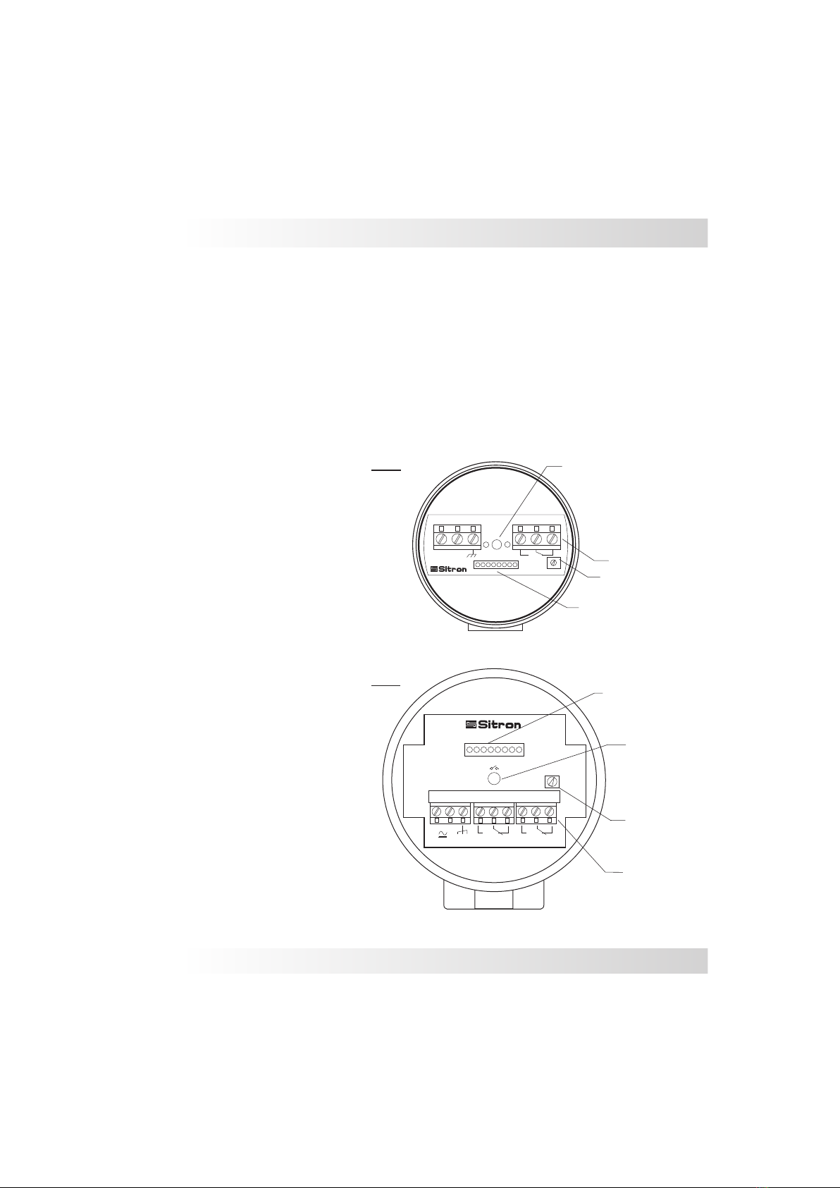
Wiring Diagram
Aluminium Enclosure (G1/G2)
2SPDT
Bargraph (B1)
Flow 100 %0
+
-
1 2 345 6 7 9
8
CF12AC
+
_
1 2 3 4 5 6
Adjust
1SPDT
Bargraph (B1)
G2
G1
1
2 - Power Supply (-)
3 - Ground
4 - NO Contact
5 - Common
6 - NC Contact
- Power Supply (+)
(P1) - Set Point Potentiometer Adjust
(B1) - 8 LED´s Bargraph: Red LED
Yellow LED
Green LED
(L1) - Central LED - Green: With flow
Red: No flow
1
2 - Power Supply (-)
3 - Ground
4 - NO Contact
5 - Common
6 - NC Contact
7 - NO Contact
8 - Common
9 - NC Contact
- Power Supply (+)
Central LED(L1)
Red/Green
Adjust (P1)
Central LED(L1)
Red/Green
Adjust (P1)
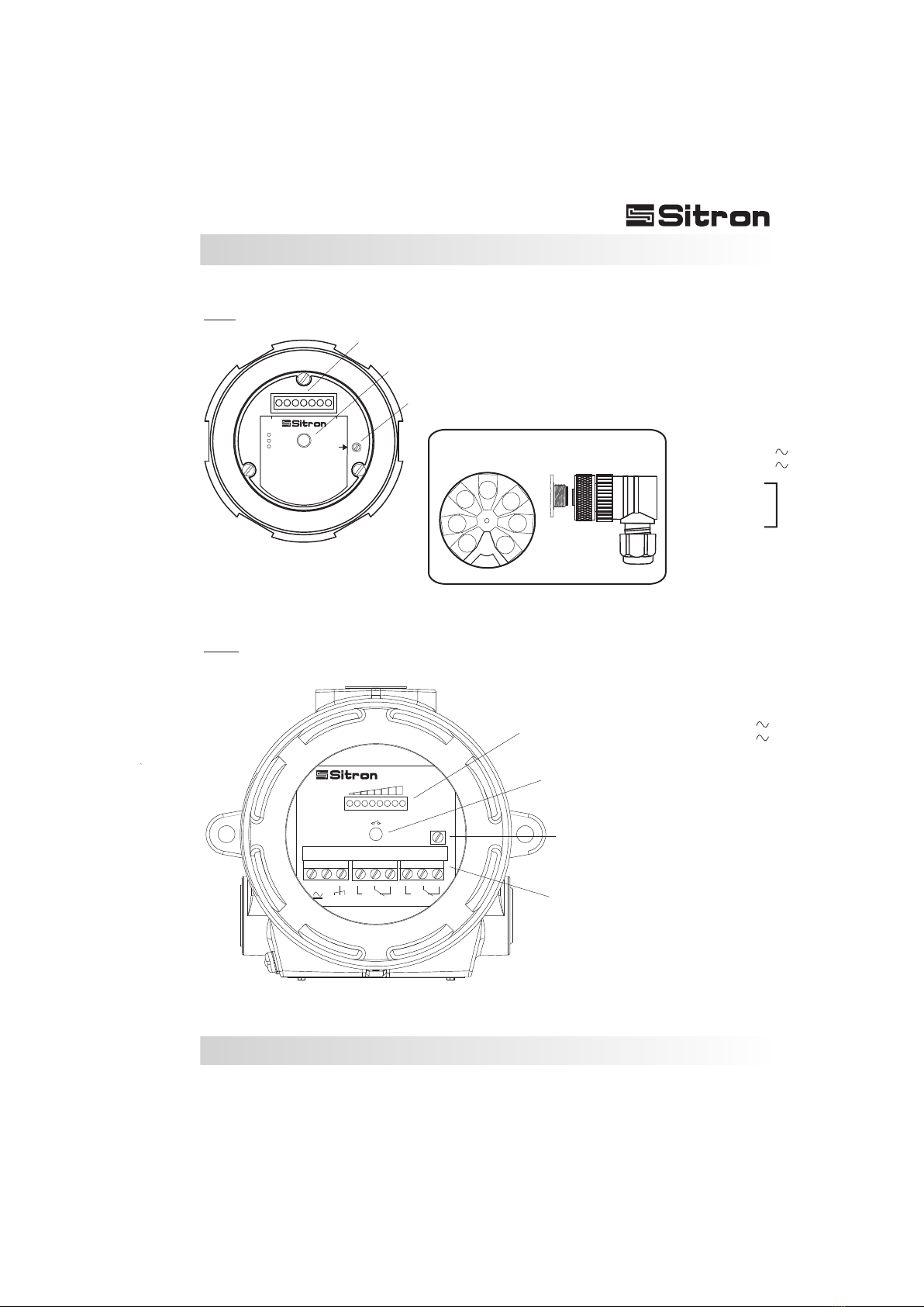
08
Wiring Diagram
(P1) - Set Point Potentiometer Adjust
(B1) - 8 LED´s Bargraph: Red LED
Yellow LED
Green LED
(L1) - Central LED - Green: With flow
Red: No flow
85...260 Vac 50/60 Hz
Adjust
Pin# 1/2 Power
Pin# 3 Ground
Pin# 4 N.O.
Pin# 5 N.C.
Pin# 6 Neutral
-Detect
-Switch
-Flow
CF12AC
G3
B1
P1
L1
1
2
3
4
5
6
7
Conector M12
8
CF12
Flow 100 %0
Adjust
5A 250Vac
+
-
1 2 345 6 7 9
8
2 SPDT
Bargraph (B1)
GX
1
2 - Power Supply
3 - Ground
4 - N.O. Contact
5 - N.C. Contact
6 - Common
7 - None
8 - None
- Power Supply
( )
( )
Central LED(L1)
Red/Green
Adjust (P1)
1
2 - Power Supply (-)
3 - Ground
4 - NO Contact
5 - Common
6 - NC Contact
7 - NO Contact
8 - Common
9 - NC Contact
- Power Supply (+)
( )
( )
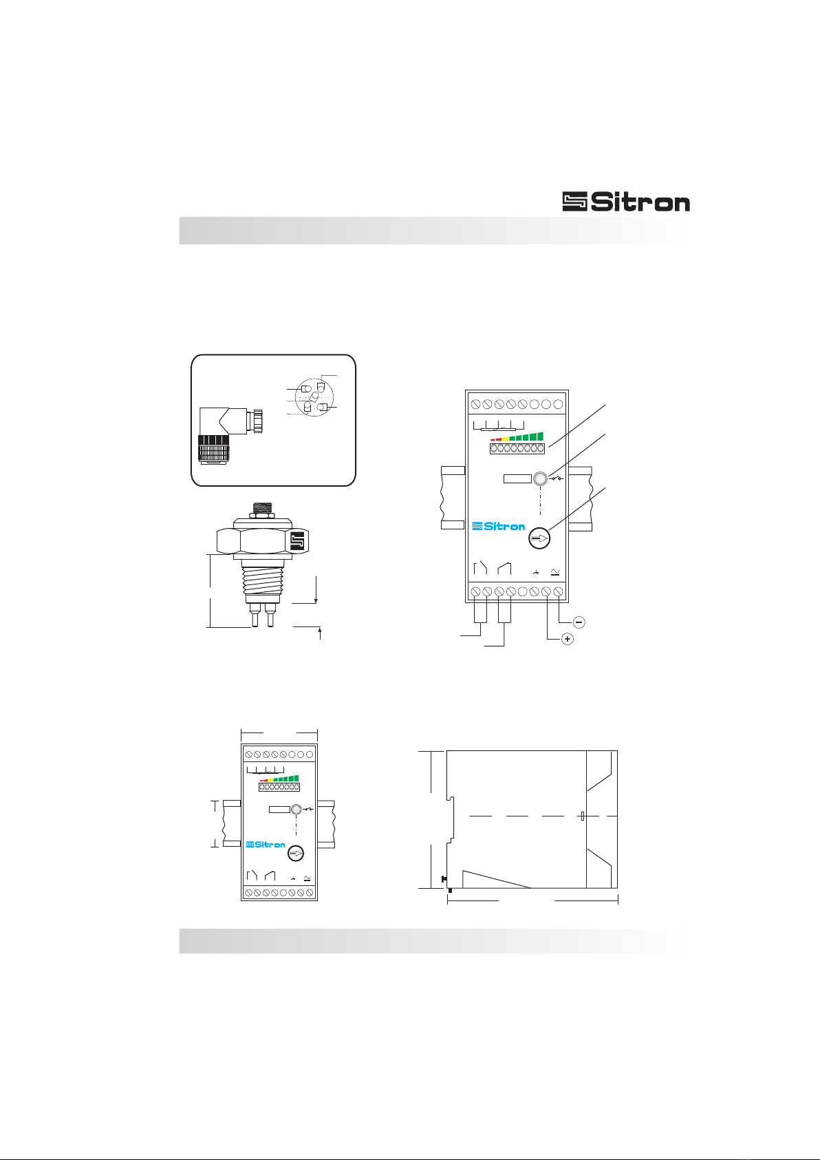
09
Wiring Diagram
12mm
L
1
VM
PR
AZ
VD
AM
2345
Adjust
678
159 11 13 141210 16
Sensor
5 A 250V ac
CF12-RM
+_
Bargraph
(24Vcc)
44mm
35mm
84mm
111mm
1
VM
PR
AZ
VD
AM
2345
Adjust
678
159 11 13 141210 16
Sensor
5 A 250V ac
CF12-RM
+_
NC
NO
Adjust
Central LED(L1)
Red/Green
Dimensions
Dimensions
F12 with CF12RM Remote Controller
CF12RM
F12
1
2 - Yellow
3 - Green
4 - Red
5 - Black
- Blue
1
5
2
3
4
10
CF12 Relay Status Guide
Application
FSH Condition
Normal
Alarm
LED Status
RED
GREEN
Set Point
OFF
ON
CF12 SPDT
Status
NO (4) NC (6)
C (5)
C (5)
Application
FSL Condition
Normal
Alarm
LED Status
GREEN
RED
Set Point
ON
OFF
CF12 SPDT
Status
NO (4)
NO (4)
NO (4)
NC (6)
NC (6)
NC (6)
C (5)
C (5)
11
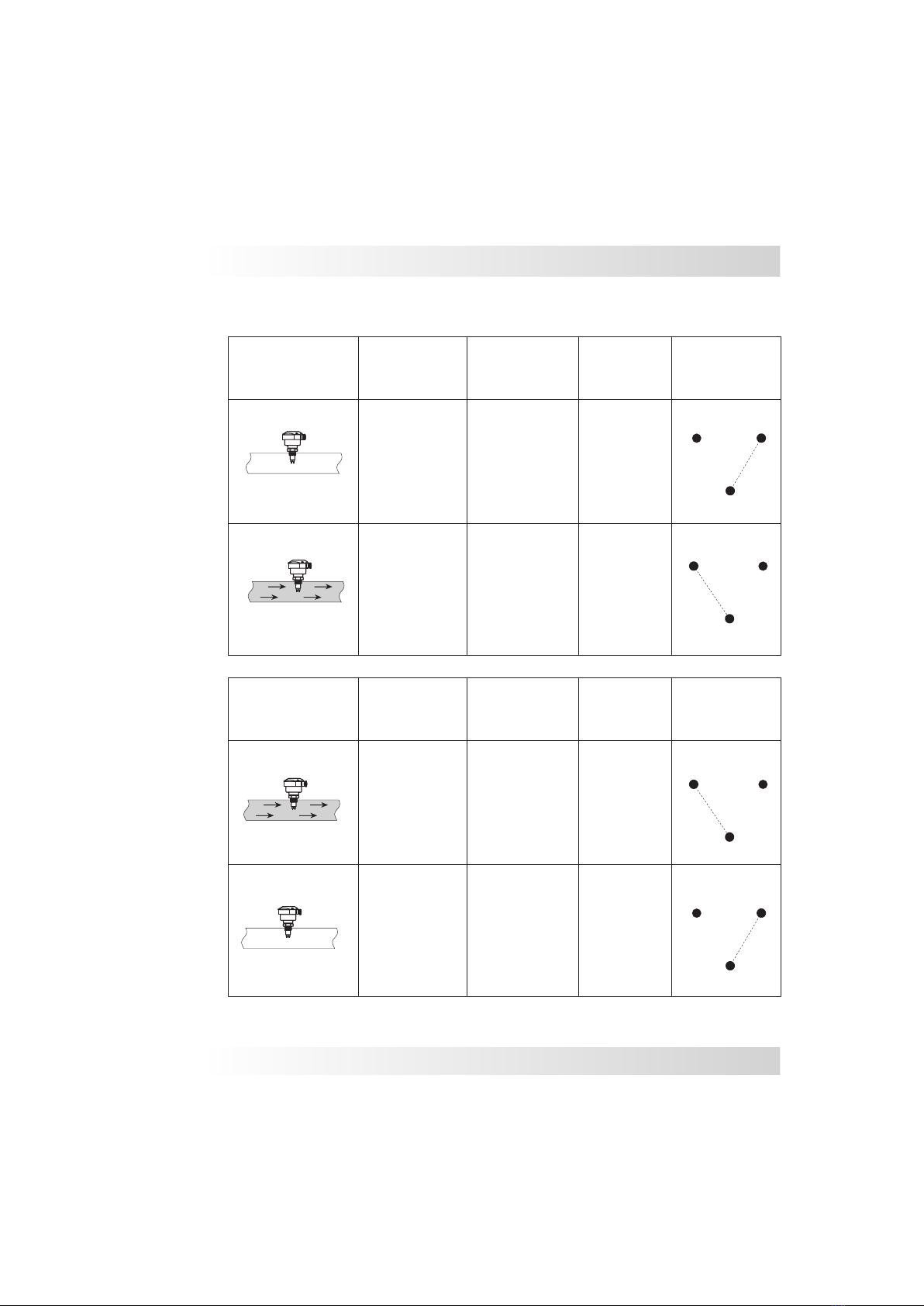
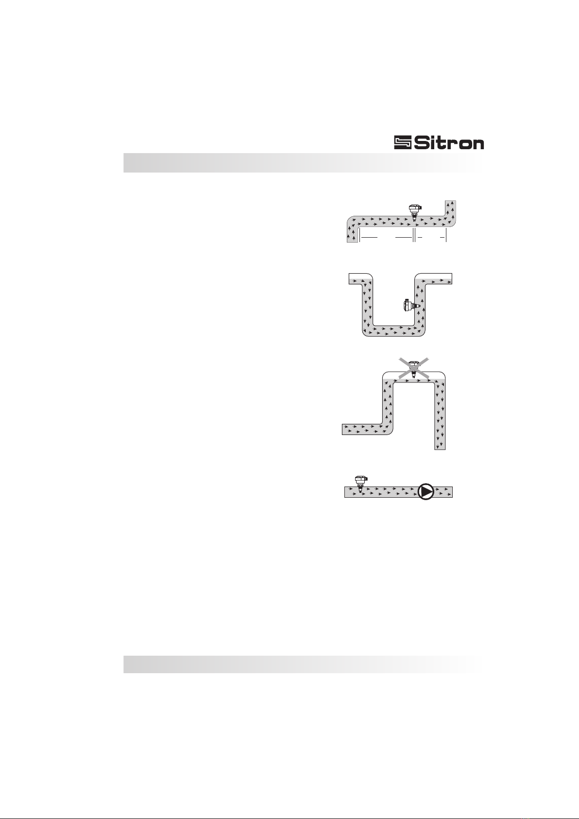
Pre-Installation
Pre-Installation Checks:
1) Its recommended that the flow switch is
installed with a distance of ½ a meter of the pipe
bent where the flow enters and 5x times the
diameter of the pipe where the flow exits, enabling
it to have an accurate reading (Fig. 1).
Verify that the installation point isn’t near any
connections, valves, elbows or anything similar,
this can cause errors in the reading of the probe
due to turbulence in the pipe.
2) It is important that the flow switch is not installed
at the highest point in the pipe run or in a location
where there is the risk of air accumulating in the
pipe. Keep in mind that the ideal mounting
location is where the pipe is always full. This will
ensure that the switch is always immersed in the
flow. (Fig. 2 correct, fig. 3 incorrect)
3) In pipes that have pressure pumps or retention
valves, we recommend that the probe be installed
before the pump due to the fact that it will have
less turbulence. (Fig. 4)
4) Confirm that the wire connections are correct
and that the available power supply is compatible
with the CF12 unit.
5) Verify that the operating pressure and
temperature of the process corresponds to the
operating parameters of the CF12 unit.
More recommendations and handling instructions
can be found on page 14.
Fig. 1
Fig. 4
Pump
Fig. 2
Fig. 3
1/2m 5xØ
Ce manuel convient aux modèles suivants
1
Table des matières


