Sitron SC404 Manuel utilisateur
USER’S GUIDE
SC404
Capacitive
Level Sensor
Installation, Operation, Maintenance Instructions

Contents
3
Introduction . . . . . . . . . . . . . . . . . . . . . . . . . . . . . . . . . . . . . . . . . . . . . . . . . 4
Models & Dimensions . . . . . . . . . . . . . . . . . . . . . . . . . . . . . . . . . . . . . . . . . 5
Wiring Diagram . . . . . . . . . . . . . . . . . . . . . . . . . . . . . . . . . . . . . . . . . . . . . . 6
Mounting Note . . . . . . . . . . . . . . . . . . . . . . . . . . . . . . . . . . . . . . . . . . . . . . 12
Installation . . . . . . . . . . . . . . . . . . . . . . . . . . . . . . . . . . . . . . . . . . . . . . . . . 13
Calibration . . . . . . . . . . . . . . . . . . . . . . . . . . . . . . . . . . . . . . . . . . . . . . . . . 17
Handling . . . . . . . . . . . . . . . . . . . . . . . . . . . . . . . . . . . . . . . . . . . . . . . . . . 19
Technical Specifications . . . . . . . . . . . . . . . . . . . . . . . . . . . . . . . . . . . . . . 20
Trouble Shooting . . . . . . . . . . . . . . . . . . . . . . . . . . . . . . . . . . . . . . . . . . . . 21
Ordering Information . . . . . . . . . . . . . . . . . . . . . . . . . . . . . . . . . . . . . . . . . 22
Terms & Conditions . . . . . . . . . . . . . . . . . . . . . . . . . . . . . . . . . . . . . . . . . 23

4
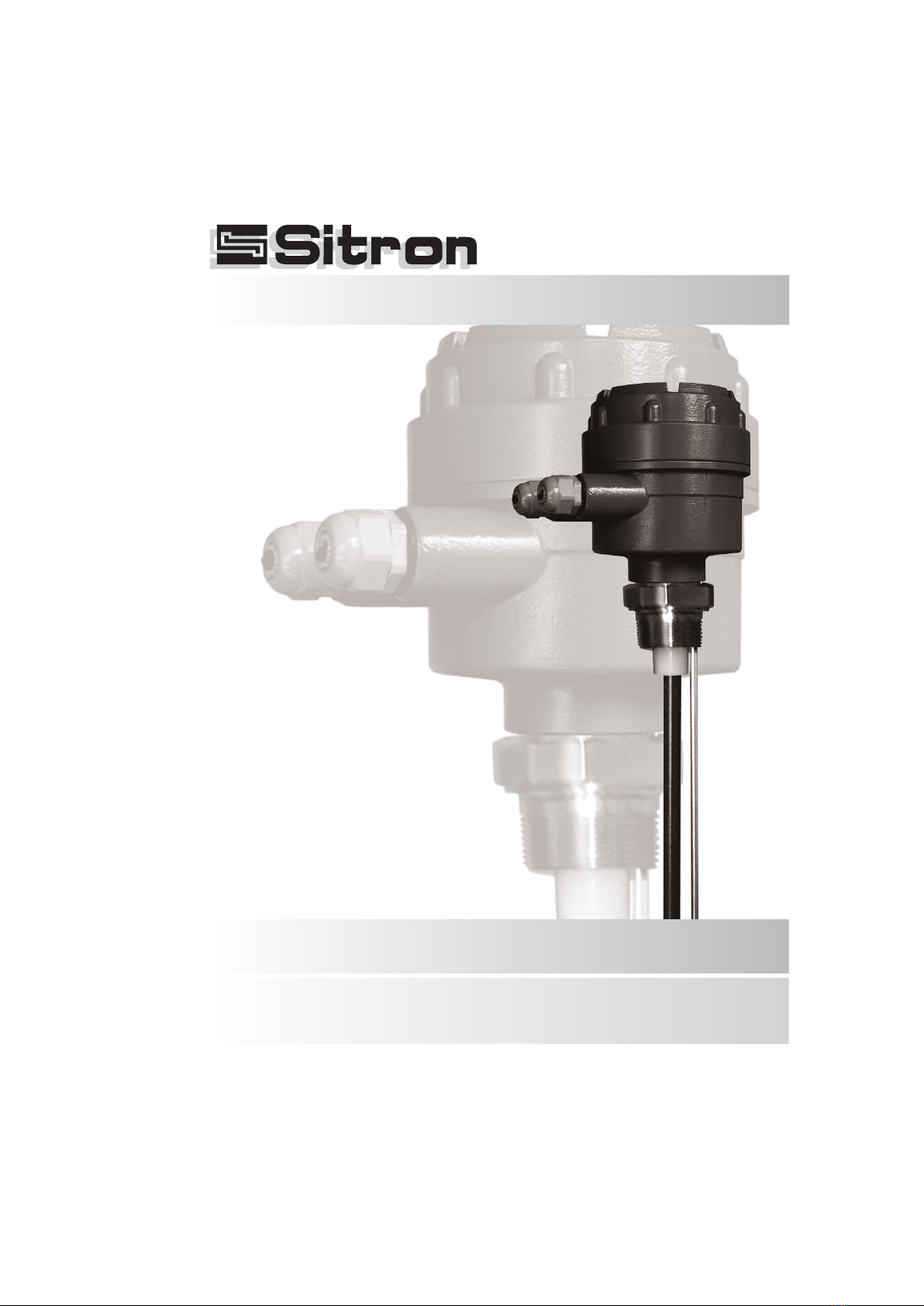
SC404 - Capacitive
Level Sensor
The SC404 is a capacitance continuous level transmitter with an
integrated electronics module mounted within the housing. This 2 wire
loop powered unit provides a 4-20mA output (galvanically isolated).
Set up and calibration is achieved with a zero and span adjustment
which works best when starting with an empty tank to set the zero and
then filling it to set the span. This flexible level measurement device
works well in many industrial processes and process media including
a variety of liquids, powders and pastes. The SC404 is made with
316SS rigid rods or 316SS cables (coatings are required for
conductive mediums) and can also be made with a secondary
reference rod or reference sheath built into the process connection.
The wide range of applications for RF analog level measurement
probes (such as liquids, pastes, solids and granules), requires
attention in selecting the correct configuration and installing it in the
proper location. To cater to all applications, Sitron's probes are offered
with different designs and features.
Wide range of applications/industries:
i.e. water, oils, corrosives, solids, powders, grains, etc.
Accurate and reliable measurement
No moving parts - Rugged construction
Can operate at high temperatures and pressure
Functions on conductive as well as non-conductive medias
Galvanic Isolation
Features
Introduction
Sitron-USA - Phone (516) 935-8001 / Fax (800) 516-1656
5
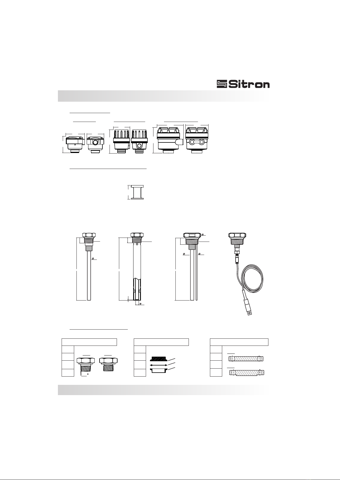
Models and Dimensions
Threaded
SC404 W/
Reference Sheath
SC404 W/
Reference Rod
SC404 w/ Cable
(also w/ reference cable)
SC404 Standard
Note: Minimal insertion for the SC404 is ½ meter
Extended necks for medium temperature (up to 120°C)
3/4”
1 ½”
1 ½”
1 ½”
2 ½”
2 ½”
1”
2”
2”
2”
3”
N1- Nylon G1-Aluminum G2 - Aluminum
1”
1,75
Tri-Clamp Flange
Housing Types
Mounting Options for SC404
Process Connections
TC Connection
ANSI 150#
ANSI 300#
Rubber Seal
Process Connection
NPT BSP FF
RF
L
20
½”
1,6
1”NPT
1”NPT
½”
½”
L
25
66
1/4”
1 1/2”NPT
L
20
50mm
126mm
130mm
130mm 118mm
89mm
76mm
89mm 80mm
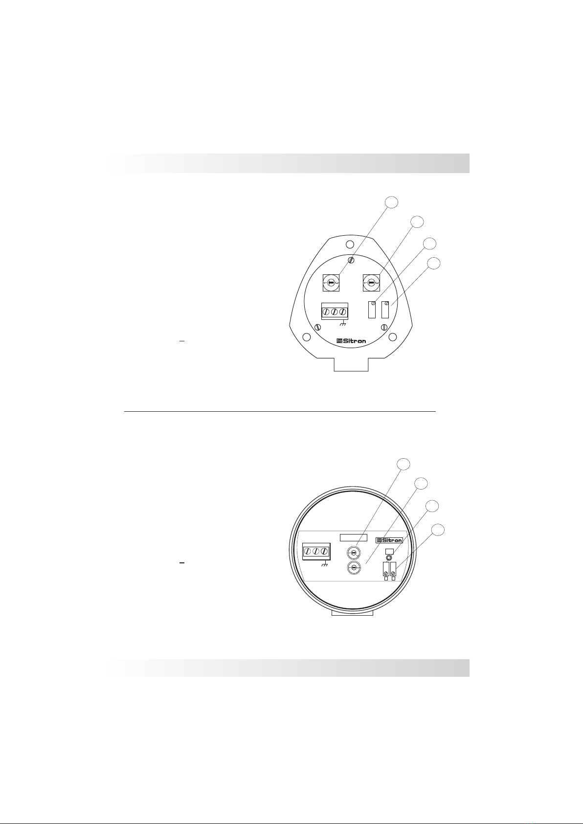
SC404 with N1 Housing
0
2
0
2
Span
Zero
Gain
SC404
Sub
+_
123
1
+_
23
0
2Gain
SC404-G
On
S
Z
SC404 with G1 Housing
1- Power Supply (+)
2- Power Supply ( )
3- Ground
24Vdc / 4...20mA
C
A
D
B
A- Adjust Sensibility (Gain)
B- Adjust Sensibility (Sub gain)
C- Adjust Zero (begin scale)
D- Adjust Span (end of scale)
A
B
C
D
1- Power Supply (+)
2- Power Supply ( )
3- Ground
24Vdc / 4...20mA
A- Adjust Sensibility (Gain)
B- Adjust Sensibility (Sub gain)
C- Adjust Zero (begin scale)
D- Adjust Span (end of scale)
Sitron-USA - Phone (516) 935-8001 / Fax (800) 516-1656
0
2
Sub
Wiring Diagram
6
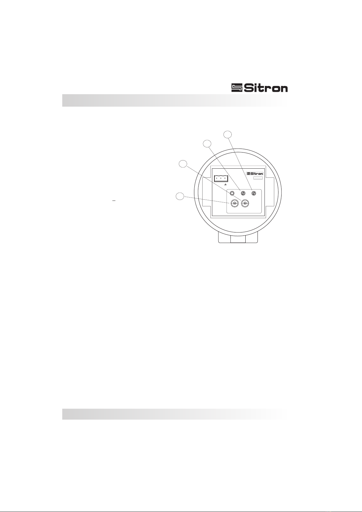
SC404 with G2
A
B
C
Wiring Diagram
1
24Vdc
(+-10%)
+
4...20mA
2
-
3
D
On
Gain
0
2
Zero
Sub
0
2
Span
SC 404
7
1- Power Supply (+)
2- Power Supply ( )
3- Ground
24Vdc / 4...20mA
A- Adjust Sensibility (Gain)
B- Adjust Sensibility (Sub gain)
C- Adjust Zero (begin scale)
D- Adjust Span (end of scale)

8
Wiring Diagram
Sitron-USA - Phone (516) 935-8001 / Fax (800) 516-1656
Galvanic Isolator - ISO420
1- Probe (+)
2- Probe( )
11- Power Supply (+)
12- Power Suppy ( ) 6mm
69.8mm
DIN 35mm
111mm
83.5mm
35mm
44mm
in 24 VDC
4...20mA
4...20mA
Zone 0
out
ISO 420
11+ -12
1+ -2
L1
in _
11+
1 + 2
_
12
4...20mA
4...20mA
Zone 0
out
ISO 420
+
-
+
-N
Security Barrier ISO 420 PLC
4...20mA
Transmitter
4...20mA
9
Wiring Diagram
Electrical connection using the Galvanic Isolator for a PLC with an active input card.
Electrical connection using the Galvanic Isolator for a PLC with a passive input card.
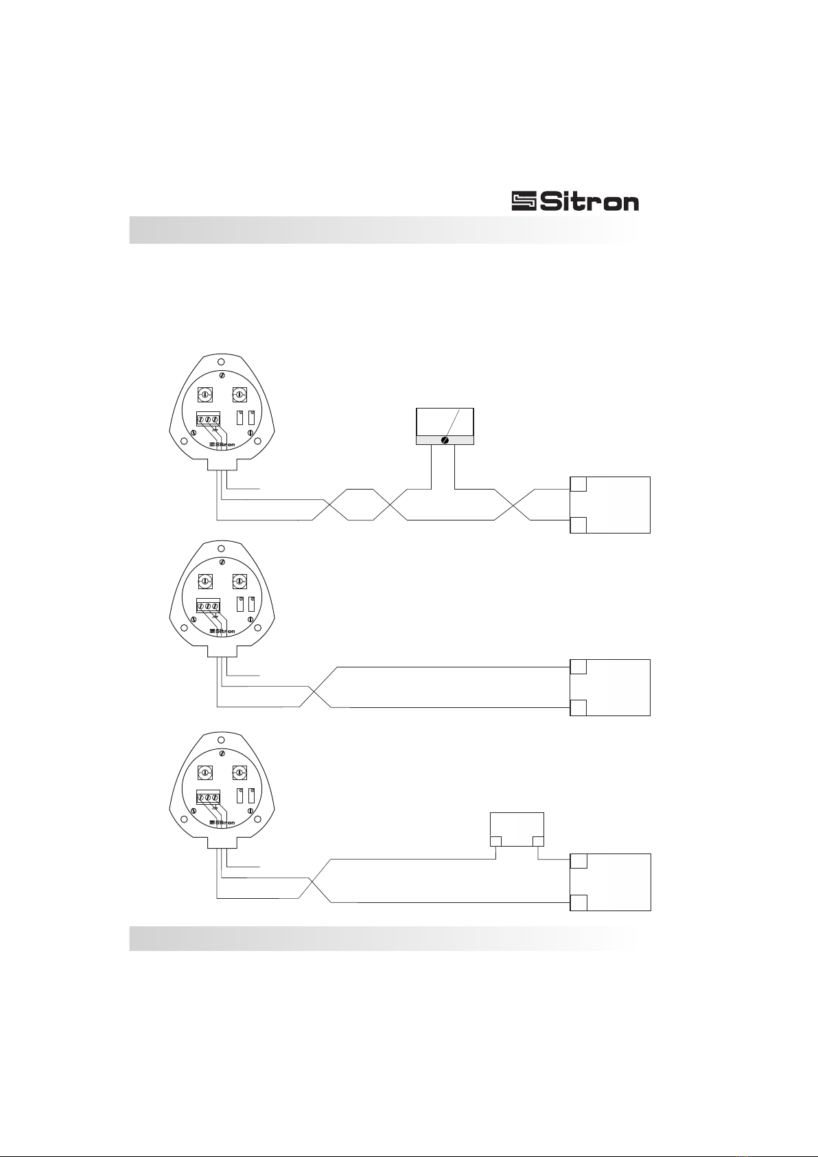
Connecting directly into the power supply
Active PLC input card
Passive PLC input card
___
+++
PLC
___
+++
Power
Supply
4 ... 20 mA
0 ... 100 %
___
___
+++
+++
Power
Supply
PLC
+
+
+
-
-
-
Ground
Ground
Ground
Different wiring scenarios for the N1 electronics
0
2
0
2
0
2
0
2
0
2
0
2
Span
Span
Span
Zero
Zero
Zero
Gain
Gain
Gain
SC404
SC404
SC404
Sub
Sub
Sub
10...30VDC
10...30VDC
10...30VDC
4...20mA
4...20mA
4...20mA
+
+
+
_
_
_
1
1
1
2
2
2
3
3
3
24Vdc
24Vdc (+/- 10%)
24Vdc (+/- 10%)
10
Wiring Diagram
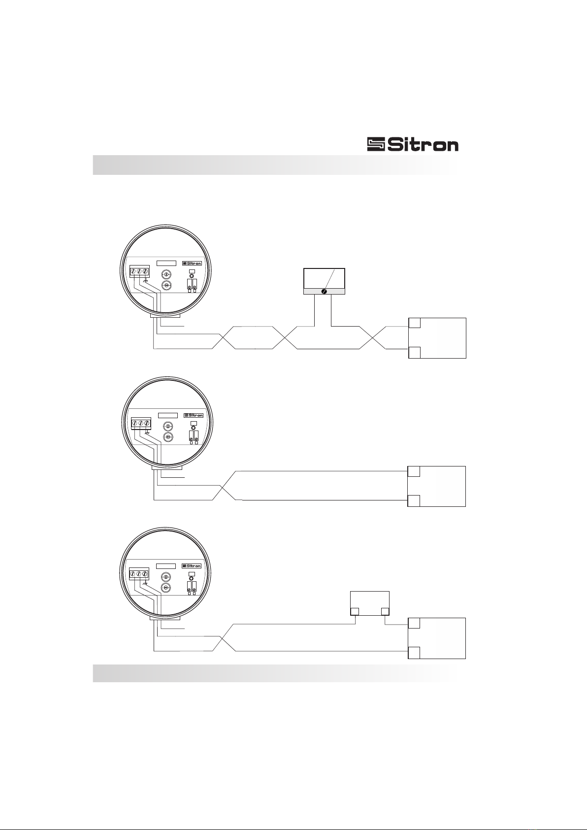
Connecting directly into the power supply
Active PLC input card
Passive PLC input card
___
+++
PLC
___
+++
Power
Supply
4 ... 20 mA
0 ... 100 %
___
___
+++
+++
Power
Supply
PLC
Different wiring scenarios for the G1 electronics
1
+_
23
V=10...30VDC
I=4...20mA
0
2
Gain
SC404-G
On
S
Z
+
-
Ground
1
1
+
+
_
_
2
2
3
3
V=10...30VDC
V=10...30VDC
I=4...20mA
I=4...20mA
0
0
2
2
Gain
Gain
SC404-G
SC404-G
On
On
S
S
Z
Z
+
+
-
-
Ground
Ground
0
2
Sub
0
2
Sub
0
2
Sub
12...30Vdc
24Vdc (+/- 10%)
24Vdc (+/- 10%)
11
Wiring Diagram
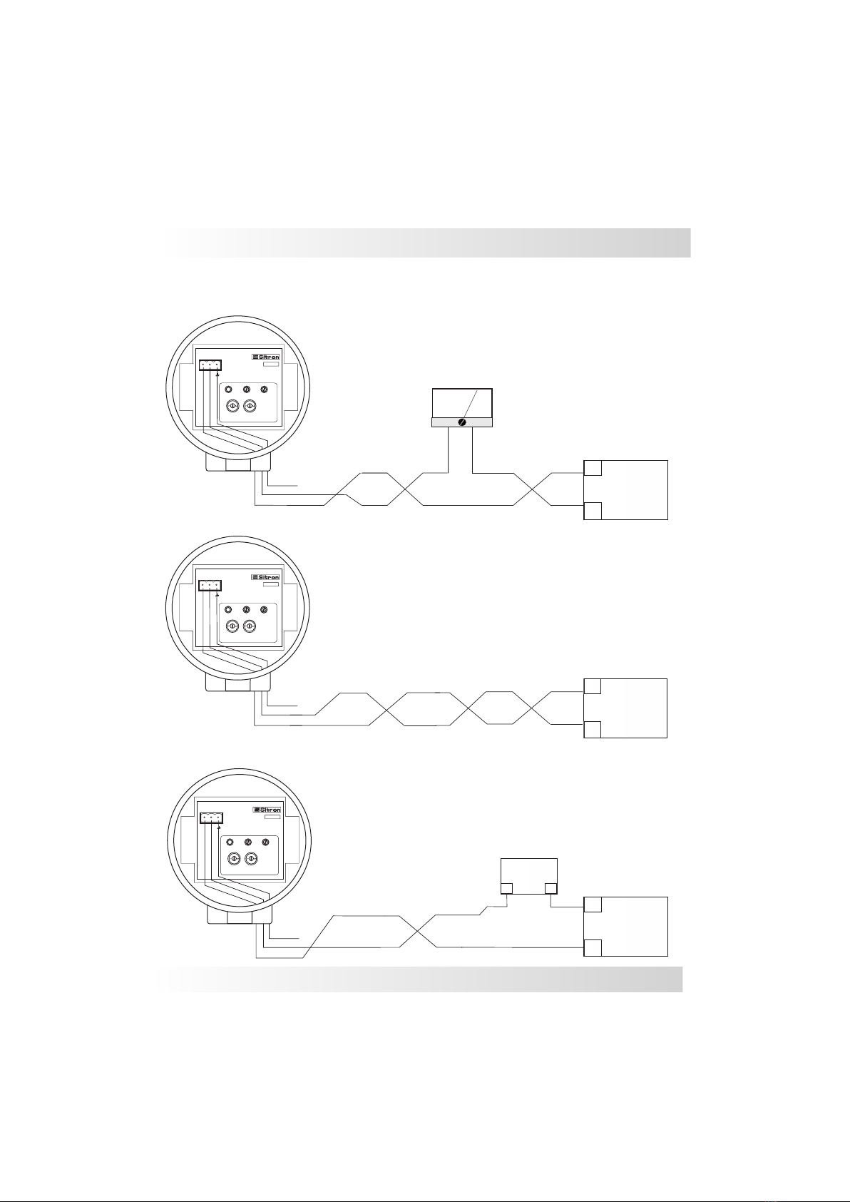
Electrical connection for a PLC with an active input card.
Electrical connection for a PLC with a passive input card.
Connecting directly into the power supply
Active PLC input card
Passive PLC input card
___
+++
Power
Supply
4 ... 20 mA
4 ... 20 mA
4 ... 20 mA
0 ... 100 %
___
___
___
+++
+++
+++
Power
Supply
PLC
PLC
+
+
+
-
-
-
Ground
Ground
Ground
Different wiring scenarios for the G2 electronics
The G2 offers a built in galvanic isolator. In this case a separate one is not necessary.
0
0
0
2
2
2
0
0
0
2
2
2
Span
Span
Span
On
On
On
Zero
Zero
Zero
Gain
Gain
Gain
Sub
Sub
Sub
1
1
1
2
2
2
3
3
3
SC 404
SC 404
SC 404
24Vdc
24Vdc
24Vdc
(+-10%)
(+-10%)
(+-10%)
+
+
+
-
-
-
4...20mA
4...20mA
4...20mA
Sitron-USA - Phone (516) 935-8001 / Fax (800) 516-1656
24Vdc (+/- 10%)
24Vdc (+/- 10%)
24Vdc (+/- 10%)
Table des matières


