User's Guide
SMB10-SN03-P22A
SMB10
Garonne
Phase/Frequency Discriminator
3.4 Jumpers
There is one jumper on the SMB10's printed circuit board.
3.4.1 Acquire/Track Jumper
This normally open jumper is used to connect the
Acquire/Track Output
to the SMA91 Autolock Con-
troller module. In order the Autolock Controller to operate, a
0
-
Ω
resistor must be mounted on the the
JMP301 footprint. Can be left open if not used.
4 Circuitry
4.1 Circuit Description
The ltered output of the microwave mixer is applied to the Beat-Note input connector SMA401. The
low-pass lter RF401 provides an additional mixer-products attenuation. By default, its cut-o frequency is
set to
900 MHz
. The coupled output (
−10 dB)
of RF402 is connected to the Beat-Note monitor connector
(SMA402) while the main output is amplied (
+20 dB
) by the RF gain-block RF403. Its output level
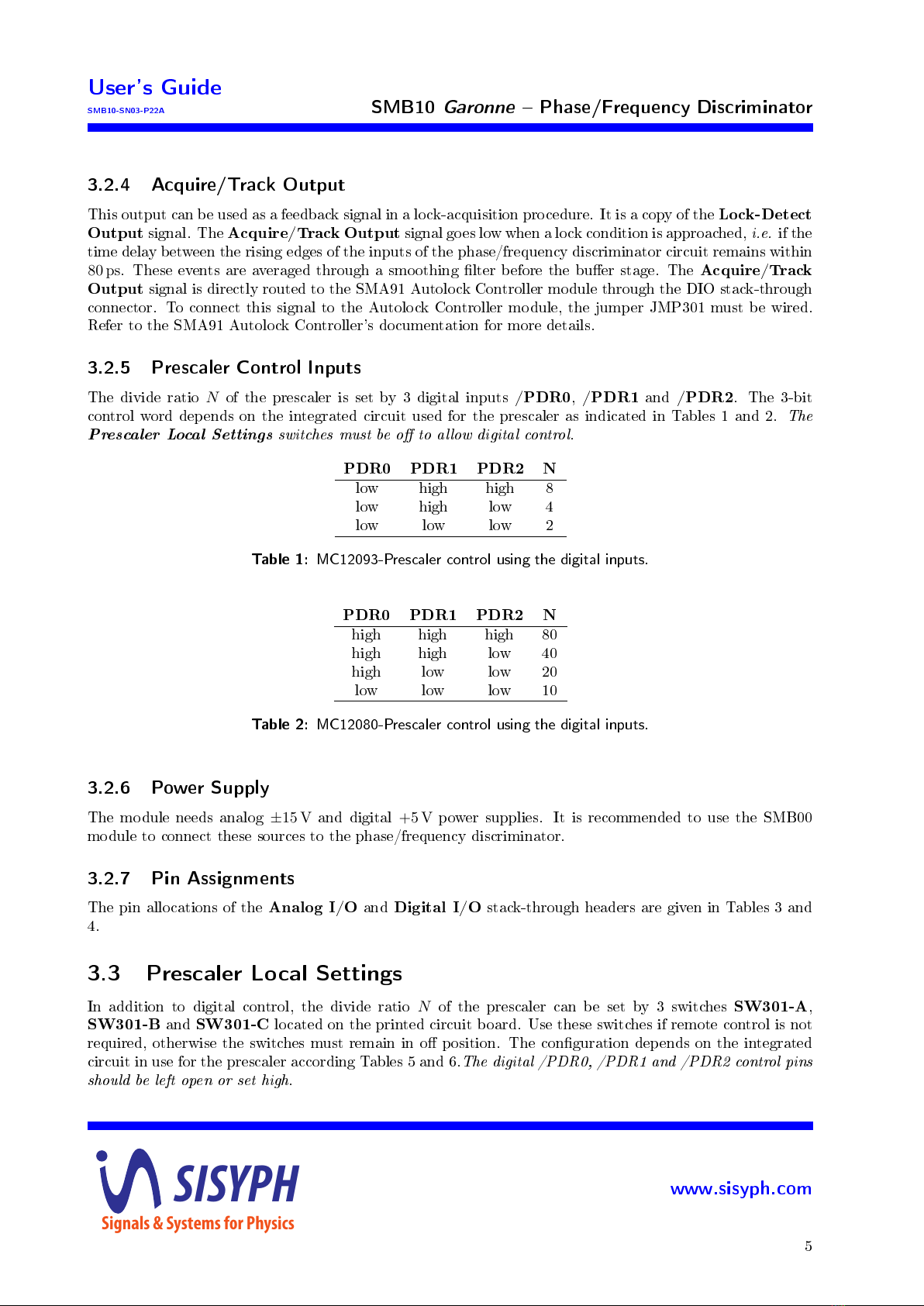
is sucient to drive the prescaler U401 MC12093 or MC12080 depending of the desired divide ratios.
Operation at
N= 1
is obtained without any prescaler circuit. In this case, the prescaler circuit has to be
removed and a zero-ohm resistor (R403) is installed. The capacitor CX401 should be replaced with an zero-
ohm resistor if the operating frequency is below
100 MHz
. If the MC12080 is used, the resistor R404 may be
required. The prescaler divide ratio is controlled by the PDR signals coming from the digital interface.
The output of the prescaler is applied to an PECL-level translator stage (U203) whose the dierential
output pair drives the feedback pins of the LVPECL phase/frequency comparator U207. The Synchronization
input is also translated into PECL levels using the U201 driver. Its outputs are also fed to the reference
terminals of U207.
The dierential output of the phase/frequency discriminator is applied to a low-pass lter reducing the
harmonics of the Synchronization signal. The shown values are calculated for an operation at
fLO = 100 MHz
.
The Phase Error signal is given by the dierential amplier U204 whose outputs are connected to the Analog
I/O bus header through 50-ohm resistors. It is possible to boost the sensitivity of the Error signal at
low frequencies by using C212/R236 and C213/R237. These components can provide an additional gain
of
+14 dB
from DC to
4 kHz
. This features is useful to increase the overall loop-gain of the OPLL. It
also increases the SNR of the measurement. The Phase Error monitor output is obtained using another
dierential amplier U202. Its provides a tenfold copy of the Phase Error signal. In order to remove the
high-frequency harmonics, an additional lter can be implemented using the capacitors C214 and C215.
The sampled and smoothed lock-detect output of the phase/frequency comparator is applied to the
comparator U205 to provide a digital signal indicating that an locked-operation is approached.
SISYPH
Signals & Systems for Physics
www.sisyph.com
7