
SIS M250 Manuel utilisateur

SIS MACHINES
TECHNICAL OPERATING MANUAL_M250/M250MA_v2.2
This operating manual is downloadable from https://siselectromed.com/
Due to periodic revisions, always check that you are reading the most up to
date version of this manual.
PLEASE READ THIS MANUAL CAREFULLY BEFORE USING THE SIS
EQUIPMENT FOR CORRECT AND SAFE OPERATION.
Page . SIS ANUFACTURING LTD, NZ. JULY 2020.

SIS MACHINE M250/M250MA MODEL OPERATING MANUAL
CONTENTS
SECTION PAGE
DELIVERY AND UNPACKING_ _ _ __ _ _ _ _ _ _ _ _ _ _ _ _ 4
WARNING FOR BIOLOGICAL APPLICATIONS _ _ _ _ _ _ _ 4
DEVICE DESCRIPTION _ _ _ _ _ _ _ _ _ _ _ _ _ _ _ _ _ _ _ 4
POWER SOURCE _ _ _ _ _ _ _ _ _ _ _ _ _ _ _ _ _ _ _ _ _ _ 5
ELECTRODE CABLE CONNECTION _ _ _ _ _ _ _ _ _ _ _ _ 5
KEYPAD CONTROLS AND OPERATION _ _ _ _ _ _ _ _ _ _ 6-7
APPLICATIONS_ _ _ _ _ _ _ _ _ _ _ _ _ _ _ _ _ _ _ _ _ _ _ _ 6
SIS electrodes_ _ _ _ _ _ _ _ _ _ _ _ _ _ _ _ _ _ _ _ _ _ 7-8
Connection of electrode cable to electrodes _ _ _ _ _ _ 7
Infection treatments_ _ _ _ _ _ _ _ _ _ _ _ _ _ _ _ _ _ _ 9
Direct Current (DC) Electrotherapy _ _ _ _ _ _ _ _ _ _ _ 10-11
DC electro-acupuncture_ _ _ _ _ _ _ _ _ _ _ _ _ _ 11
DC battlefield electro-acupuncture (BFA)_ _ _ _ _ 11-12
Transcranial DC stimulation (tDCS)_ _ _ _ _ _ _ _ 12
Low intensity DC current microcurrent electrical
neuromuscular stimulation ( ENS) _ _ _ _ _ _ _ _
12-13
Scar pain treatment _ _ _ _ _ _ _ _ _ _ _ _ _ _ _ _ 13
Ionic solution medication iontophoresis_ _ _ _ _ _ 13-14
Cell apoptosis stimulation_ _ _ _ _ _ _ _ _ _ _ _ _ 14-15
Laboratory and research use_ _ _ _ _ _ _ _ _ _ _ 15
AUDIO AND VISUAL ALERTS_ _ _ _ _ _ _ _ _ _ _ _ _ _ _ _ 16
Page 2. SIS ANUFACTURING LTD NZ. JULY 2020.

SIS MACHINE M250/M250MA MODEL OPERATING MANUAL
ELECTROTHERAPY ELECTRODE↔SKIN CONTACT _ _ _ 17-18
CONTRAINDICATIONS AND SAFETY_ _ _ _ _ _ _ _ _ _ _ _ 19
EDICAL DISCLAI ER _ _ _ _ _ _ _ _ _ _ _ _ _ _ _ _ _ _ _ 20
WATER TREAT ENT_ _ _ _ _ _ _ _ _ _ _ _ _ _ _ _ _ _ _ _ _21
AINTENANCE _ _ _ _ _ _ _ _ _ _ _ _ _ _ _ _ _ _ _ _ _ _ _ 22
WARRANTY_ _ _ _ _ _ _ _ _ _ _ _ _ _ _ _ _ _ _ _ _ _ _ _ _ _23
Returns, Disposal _ _ _ _ _ _ _ _ _ _ _ _ _ _ _ _ _ _ _ _24
DEVICE SPECIFICATIONS _ _ _ _ _ _ _ _ _ _ _ _ _ _ _ _ _ 25
ANUFACTURER'S DECLARATION_ _ _ _ _ _ _ _ _ _ _ _ _26
Page 3. SIS ANUFACTURING LTD NZ. JULY 2020.
SIS MACHINE M250/M250MA MODEL OPERATING MANUAL
DELIVERY AND UNPACKING
Please unpack the shipping package carefully and inspect contents
immediately on receipt. Check that all ordered equipment is included in the
shipping box and notify SIS anufacturing Ltd New Zealand immediately of
any missing items from your order.
Visible damage or tampering to shipping boxes must be recorded before
signing the delivery receipt. Please take photographs of any received
damaged items. Report the damage or tampering immediately to the shipping
carrier. You must also notify SIS anufacturing Ltd immediately of any
received damaged or tampered items or of any lost shipments.
WARNING FOR BIOLOGICAL APPLICATIONS
THE SIS ACHINES ODELS 250/ 250 A ARE ELECTRONICALLY
CALIBRATED WITH EXTRE E PRECISION FOR THERAPEUTIC
BIOLOGICAL ELECTRICAL STI ULATION IN CO BINATION WITH THE
SIS SILVER-NYLON ELECTRODES. USE OF OTHER ELECTRODES CAN
CAUSE ADVERSE AND UNPREDICTABLE BIOLOGICAL EFFECTS. FOR
OTHER BIOLOGICAL ELECTRICAL STI ULATION APPLICATIONS, IF SIS
SILVER-NYLON ELECTRODES ARE NOT USED, ONLY USE SURFACE,
INSERTED OR I PLANTED ELECTRODES APPROVED FOR BIOLOGICAL
CONTACT AND EDICAL/THERAPEUTIC APPLICATIONS. READ THE
CONTRAINDICATIONS AND SAFETY INSTRUCTIONS IN THIS ANUAL
BEFORE USING THIS EQUIP ENT.
DEVICE DESCRIPTION
The SIS machines 250/ 250 A models are designed for electromedical,
nanoampere to low milliampere direct current (DC) electrotherapy
applications, and for low intensity (amperage) DC silver iontophoresis
stimulation (SIS) when used with SIS electrodes. The 250 A model can be
used for liquid medication intophoresis, and for cell apoptosis stimulation.
The 250/ 250 A models are also designed for use as a nanoampere to
low milliampere ( 250 A only) constant current generators for non-medical,
non-therapeutic, non-diagnostic, research, laboratory and experimental
purposes, including Life Sciences, and water treatment.
Page 4. SIS ANUFACTURING LTD NZ. JULY 2020.

SIS MACHINE M250/M250MA MODEL OPERATING MANUAL
. POWER SOURCE
The 250/ 250 A is powered by replaceable AAA type batteries.
Rechargeable batteries can be used and do not compromise the correct
function of the device. Refer to section 15. DEVICE SPECIFICATIONS for
further information.
Do not use zinc-carbon batteries that can leak and damage the device.
. . INSERTING AAA BATTERIES
A. POWER OFF the device if it is operating.
B. Remove the shockproof silicon cover from the casing.
C. Remove the battery compartment cover.
D. Insert 3×AAA batteries. Ensure correct polarity of the batteries—follow
the battery diagram and polarity symbols inside the battery
compartment.
E. Replace the battery compartment cover.
F. Replace the shockproof silicon cover over the casing.
2. ELECTRODE CABLE CONNECTION
2. . CONNECTION OF ELECTRODE CABLE (HARNESS)
Unplug the Seal Cap from the connection socket (Jack) in the top end panel
of the device. Insert the cable connector plug all the way into the connection
socket. Screw tighten the Locking Ring on the cable connector plug to the
socket; DO NOT use excessive force.
2.2. CABLE TESTING
Perform a cable connection and integrity test from the CABLE TEST screen
before each application.
Page 5. SIS ANUFACTURING LTD NZ. JULY 2020.
SIS MACHINE M250/M250MA MODEL OPERATING MANUAL
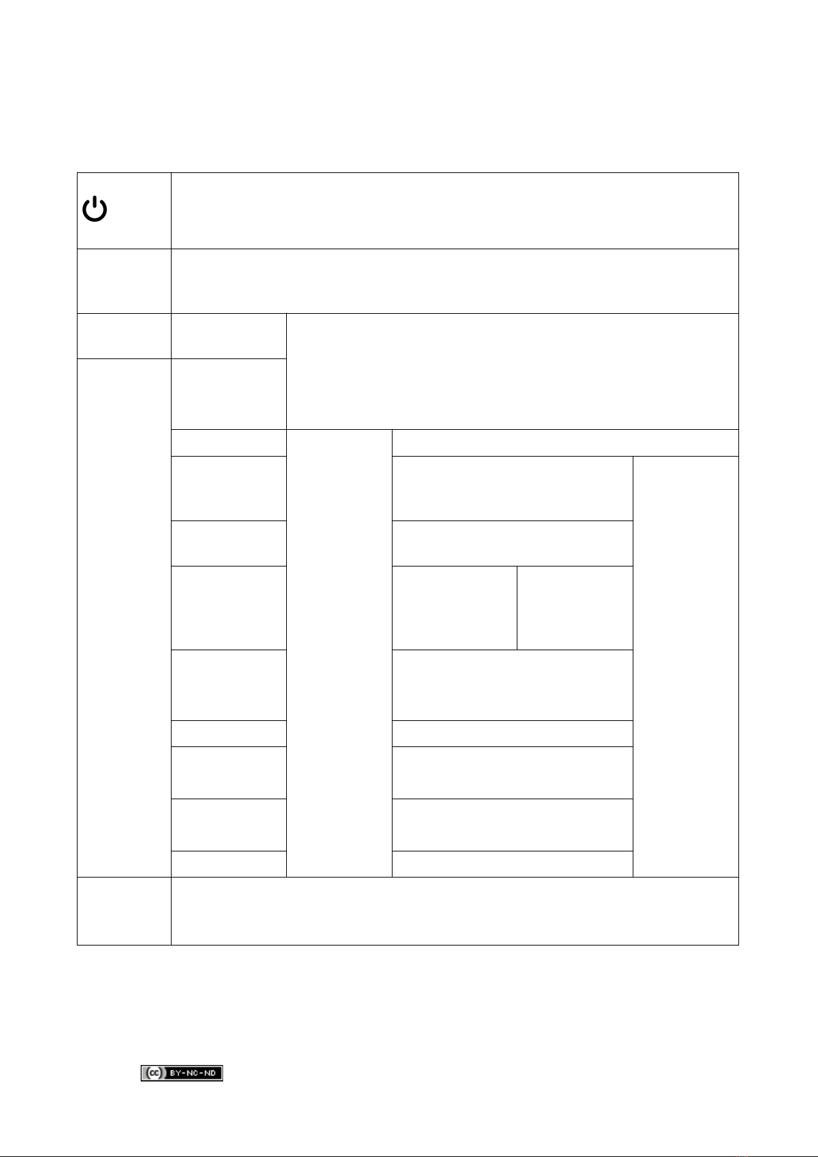
3. KEYPAD CONTROLS AND OPERATION
POWER
ON OFF
Power device ON, 2 seconds hold.
Power device OFF, 5 seconds hold.
ain
Operating
Screen
Output CURRENT and STATUS displayed
PROGRAM Access ain
enu
scroll
through ain
enu options
EXIT
PROGRAM
to select
Return to ain Operating Screen
STIM DATA
Output Current and Voltage
and measured bioelectric
data
PROGRAM
or
return to
ain enu
STATISTICS Electrode stimulation
efficiency data
CABLE TEST
Instructions
PROGRAM
Instructions 2
PROGRAM
Result:
PASSED
or
FAILED
DISPLAY
AUTO-OFF (DEFAULT) or
ALWAYS ON
TIMER Session duration data
MONITORING
AUTO (DEFAULT) or OFF
POLARITY
AUTO (DEFAULT) or OFF
ABOUT Information about device
DISPLAY
Sound turned ON or OFF, 2 seconds hold.
OLED display turned ON or OFF, 1 second hold, when DISPLAY set to
AUTO-OFF (DEFAULT).
The default device settings after powered on are OLED display and sound
turned on.
Page 6. SIS ANUFACTURING LTD NZ. JULY 2020.

SIS MACHINE M250/M250MA MODEL OPERATING MANUAL
If no keypad input is detected during normal STATUS: OK operation and the
AUTO-OFF default DISPLAY setting has not been changed to ALWAYS ON,
then the display turns off after 2 minutes for power saving.
At any time when the menu is accessed, if no user input is detected after 2
minutes, the device automatically powers off.
The red BATTERY CHARGE LED flashes every 5 seconds while the device
is operating; the LED is not under user control.
APPLICATIONS
4. SIS electrodes
NOTE: Position and secure the SIS electrodes to the body first, and then
connect the SIS electrode cable to the two SIS electrode wires.
NOTE: Read and follow the INSTRUCTIONS FOR USE (IFU) on the IFU card
included in each SIS electrode pack.
4. . Electrode size
4. . . INTERNAL INFECTIONS
The SIS (+)positive electrode must completely 'cover' a target internal organ
or other anatomical structure or area. The electrode must be at least the
same size or slightly larger than the target internal organ or other anatomical
structure as it would be seen two dimensionally in a diagnostic X-ray/CAT
scan/ RI scan/ultrasound taken from the position and anatomical plane of
the electrode on the body surface.
The SIS (-)return electrode should be (approximately) the same size or larger
than the SIS (+)positive electrode.
4. .2. SURFACE INFECTIONS
Use an SIS electrode size that most closely matches the dimensions of the
opposite sides of the area of the infection, where the electrodes will be
positioned. For example, for an area of infection that can be totally contained
within a 2cm×10cm rectangle, the 4.75cm diameter⌀ round SIS electrodes
should be applied next to the 2cm length sides of the infected area, or the
10cm×15cm SIS electrodes should be applied across the 10cm length sides.
Page 7. SIS ANUFACTURING LTD NZ. JULY 2020.

SIS MACHINE M250/M250MA MODEL OPERATING MANUAL
NOTE: Do not use over-sized SIS electrodes. The 250/ 250 A can more
accurately monitor electrode↔skin contact the smaller the electrode size.
4.2. Securing SIS electrodes
The contact of the entire surface of an electrode placed onto non-damaged
skin should be as uniform as possible to surface anatomy geometry.
NOTE: The silver-nylon side of an SIS electrode is the active surface that
contacts the body.
Use adhesive fixation tape, stretch strap, bandages or other emergency
means to secure the electrode to the body; adhesive tape should extend
beyond all edges of the electrode.
! IMPORTANT INFORMATION:
RECOMMENDED ELECTRODE LIFETIME FOR SEVERE INFECTION :
SIS (+)POSITIVE (RED WIRED) ELECTRODE: 2-24 HOURS
SIS (-)RETURN (BLACK WIRED) ELECTRODE: 2-48 HOURS
4.3. Connection of electrode cable to electrodes
●The SIS electrode that is connected to the red wire of the electrode
harness is the SIS (+)positive electrode.
●The SIS electrode that is connected to the black wire of the electrode
harness is the SIS (-)return electrode.
Insert the two gold metal 'banana plugs' at the ends of the black and red wires
of the electrode cable into the two white plastic connectors at the ends of the
SIS electrode wires; insert the 'banana plugs' all the way in until they are no
longer visible.
NOTE: Do not tape the connections of the electrode cable to the electrode
wires as doing so can cause excessive mechanical force on the cable
connection to the electro-stimulator.
Page 8. SIS ANUFACTURING LTD NZ. JULY 2020.

SIS MACHINE M250/M250MA MODEL OPERATING MANUAL
5. Infection treatments
! NOTE: The SIS machines 250/ 250 A can be targeted at almost any
infected anatomical structure or location. However, the devices cannot
determine the type of microbe(s) present; standard diagnostics and
differentiating information based on anatomical location, clinical signs,
presentation and/or laboratory testing must be applied.
5. . Electrode positioning
Diagrams of typical SIS electrode positionings for common infections are
available from: https://siselectromed.com/applications
NOTE: Avoid positioning electrodes over bones wherever possible.
5. . . INTERNAL INFECTION
A. Position the SIS (+)positive electrode onto intact skin skin directly over
the target infected organ or other anatomical structure.
B. Position the SIS (-)return electrode onto intact skin on the opposite
anatomical surface of the body to the SIS (+)positive electrode so that
the target infected organ or other anatomical structure is aligned bet ween
the two SIS electrodes.
5. .2. SURFACE INFECTION
A. Position the SIS (+)positive and (-)return electrodes on opposite side s
across and as close as possible to the target infected area ; do not place
electrodes on the infected area.
6. OUTPUT CURRENT
Adjust and PROGRA the output CURRENT for either a bacterial or
viral infection treatment:
➔B acteri al infection treatment or in vitro anti-bacterial effect: use the
default output CURRENT setting of 2.5 microAmps.
➔V iral infectio n treatment or an in vitro anti-viral effect: adjust the output
CURRENT to 7.5 microAmps.
Page 9. SIS ANUFACTURING LTD NZ. JULY 2020.

SIS MACHINE M250/M250MA MODEL OPERATING MANUAL
7. Direct Current (DC) Electrotherapy
The 250 ( 250 A) is a multirole microcurrent (and milliampere) electro-
stimulator.
If necessary, use the alligator clip adapters supplied with the SIS machine to
convert the 250/ 250 A electrode harness for connection to many other
electrodes. Insert the gold 'banana plugs' at the ends of the black and red
wires of the electrode harness into the plastic connector ends of the adapters.
7. . OUTPUT CURRENT POLARITY
(+)positive conventional current polarity is produced by the 250/ 250 A.
The black-wired ‘banana plug’ of the electrode cable is the conventional
(-)negative terminal (electrode). The red-wired ‘banana plug’ is the
conventional (+)positive terminal (electrode). That is, there is a galvanic cell
polarity current flow out of the device.
7.2. OUTPUT CURRENT POLARITY REVERSAL
The 250/ 250 A reverses the direction of current flow for 10 seconds
every 10 minutes. This function has been factory programmed for use of the
device with SIS electrodes, for removing electro-chemical debris from the
active surfaces of the electrodes resulting from the reduction and oxidation
reactions from the applied electric voltages.
NOTE: For most DC applications where other non-SIS electrodes are used,
this function is not required and can be turned OFF in the POLARITY screen.
7.3. ELECTRODE STIMULATION EFFICIENCY (ESE)
MONITORING
The 250/ 250 A monitors the contact of the SIS or other electrode(s) with
the body, or with the stimulation target for in vitro applications, in real-time
and statistically via complex measurement, logging and assessment
algorithms with self-adaptive AI aspects. The highly summarized logged ESE
data are shown in the STATISTICS screen.
ESE monitoring can be turned OFF for various DC electrotherapy applications
in the ONITORING screen. When ESE is disabled, no data are shown in the
STI DATA and STATISTICS screens.
Page 0. SIS ANUFACTURING LTD NZ. JULY 2020.
Ce manuel convient aux modèles suivants
1
Table des matières
Autres manuels SIS Équipement médical


