N2 - N5 Series
NOTICE: ALL N2 to N5Series actuators rotate CW to CLOSE the OUTPUT shaft out the bottom
of the actuator when viewed from ABOVE. On ALL N2 and N3 models, the CAM
shaft and the INDICATOR rotate CW to close as well.
TECHNICAL INFORMATION
N2V... N3V...
ACTUATOR SPECIFICATIONS
Supply Torque Output (lbf-in / Nm) 880 / 100 1770 / 200
12VAC
-
12VDC
Current Draw (Start / Run / LRA) 7.2A / 5.2A / 17.8A 7.2A / 5.2A / 17.8A
Speed (90°) DC, seconds 14 28
Motor - 12vdc Perm Magnet Brush Type 25W 25W
Duty Cycle (on/off / mod) 75% 75%
Motor Starts, per hour, Max 1200 1200
Motor Protection, Temp / Class 135°C / Class F 135°C / Class F
24VAC
-
24VDC
Current Draw (Start / Run / LRA) 4.2A / 3.2A / 11A 4.2A / 3.2A / 11A
Speed (90°) DC, seconds 14 28
Motor - 24vdc Perm Magnet Brush Type 25W 25W
Duty Cycle (on/off / mod) 75% 75%
Motor Starts, per hour, Max 1200 1200
Motor Protection, Temp / Class 135°C / Class F 135°C / Class F
120V
Current Draw (Start / Run / LRA) 1.16A / 0.93A / 1.47A 1.16A / 0.93A / 1.47A
Speed (90°) 60Hz / 50Hz, seconds 16 / 19 33 / 39
Motor - 120vac Split-Phase Cap TENV 40W 40W
Duty Cycle (on/off / mod) 25% / 75% 25% / 75%
Motor Starts, per hour, Max 1200 1200
Motor Protection, Temp / Class 135°C / Class F 135°C / Class F
230V
Current Draw (Start / Run / LRA) 0.54A / 0.42A / 0.66A 0.54A / 0.42A / 0.66A
Speed (90°) 60Hz / 50Hz, seconds 16 / 19 33 / 39
Motor - 230vac Split-Phase Cap TENV 40W 40W
Duty Cycle (on/off / mod) 25% / 75% 25% / 75%
Motor Starts, per hour, Max 1200 1200
Motor Protection, Temp / Class 135°C / Class F 135°C / Class F
All
Electrical Entry (2) 3/4" EMT or ABS gland
Control On/Off or Proportional
Ambient Operating Range -22°F to +125°F / -30°C to +52°C
Humidity Range 0-95% RH
Altitude Limit 9850 ft / 3000 m
Table of Contents
1 ................... Product Safety Information
2 ................... Product Specifications
3 ................... Shipping and Handling
3 ................... Installation Notices
3 & 8
................... Product Mounting and Setup
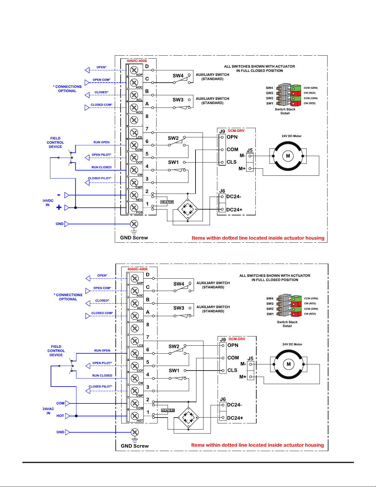
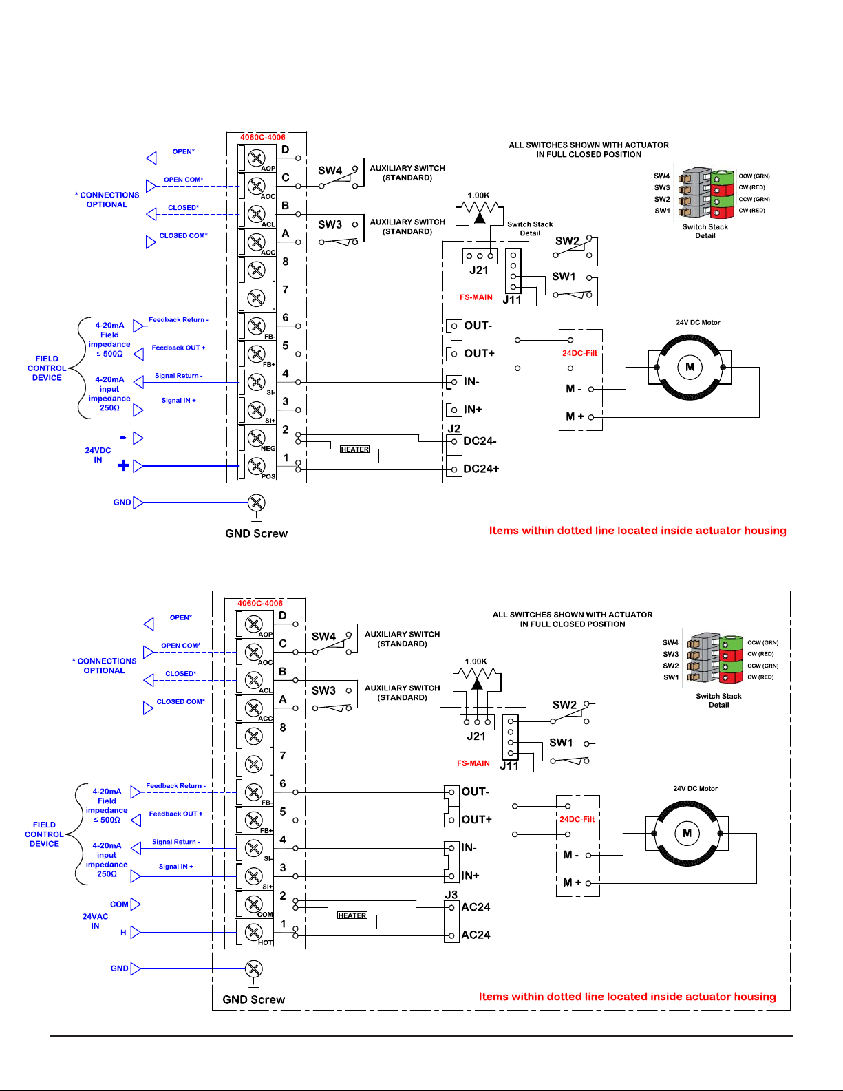
4 ~ 7................ Wiring Diagrams
8.................. Wiring Information and Control
9.................. Adjusting the actuator CW Stop Position
10 .................. Adjusting the actuator CCW Stop Position
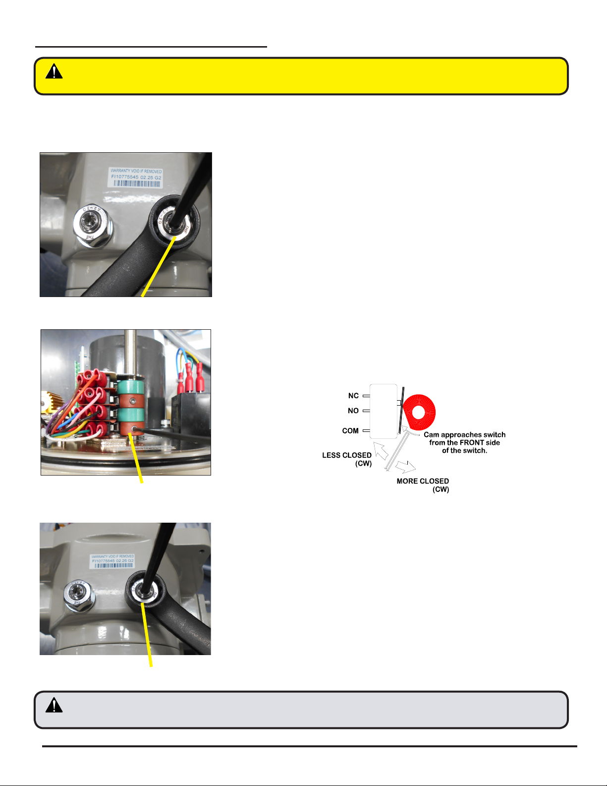
11.................. Adjusting the actuator Auxiliary switch cams
12.................. Calibrating and Commissioning On/Off Models
13
.................. PCB Reference Data
14~18 ............... Calibrating and Commissioning Proportional Models
19.................. Mechanical Data
20.................. Component Identification
21&22
.............. Troubleshooting
IOM16 N2, N5
070716 Page 2 of 23
www.siral.us