II. PLUMBING CONNECTIONS
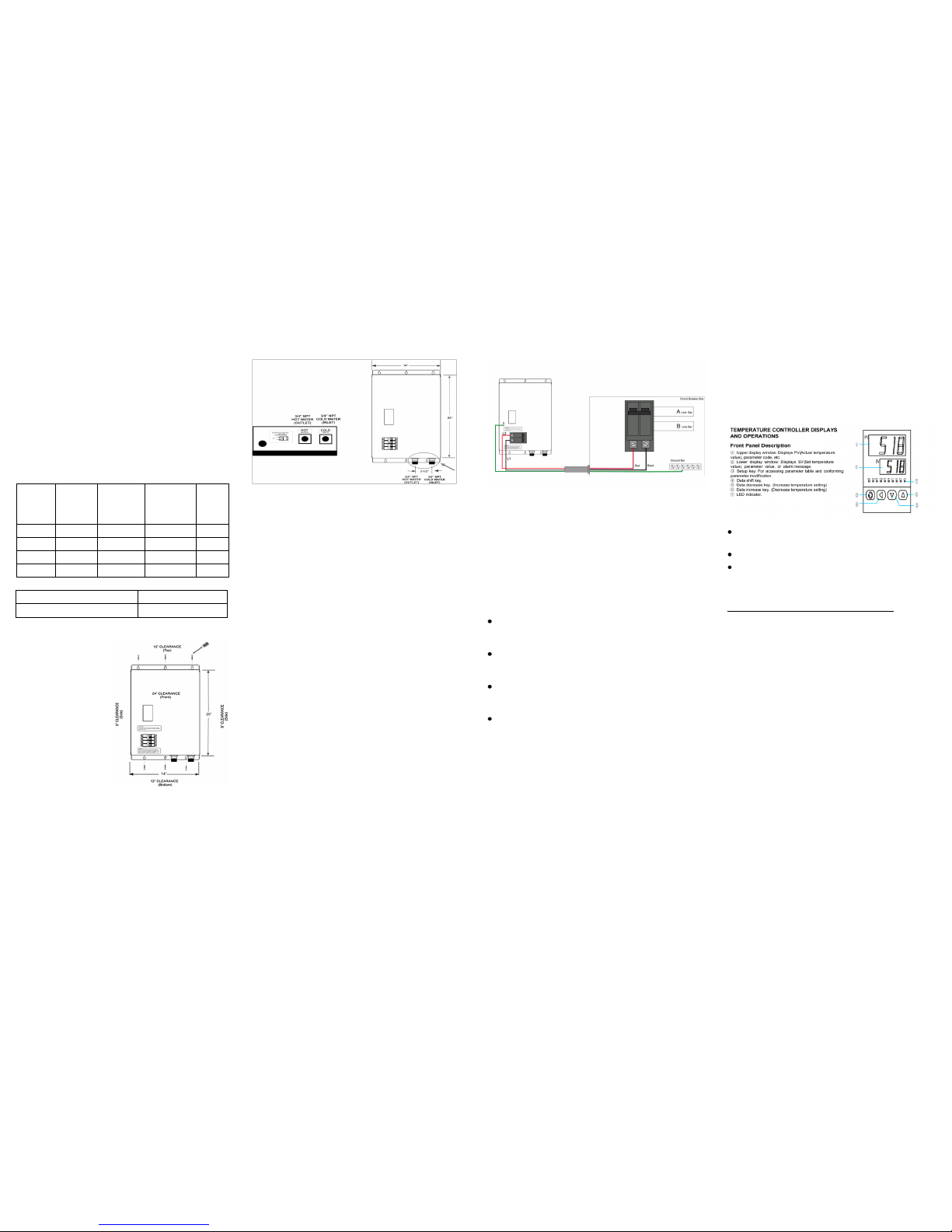
INLET AND OUTLET CONNECTIONS: The inlet and outlet
connections are clearly marked on the unit. They each have a 3/4”
NPT connector. The cold water inlet is on the right hand side and
the hot water outlet is on the left hand side. Under NO
circumstances can these be reversed, reverse cause the unit to be
inoperable.
ISOLATION VALVES: Install isolating valves (ball valve type) on
both inlet and outlet water line. This valve can be used to turn off
the water supply to the unit if it needs servicing or maintenance
purposes.
PRESSURE RELIEF VALVE: You should check the local codes to
find which type of PRV is required in your area. The use of one 3/4"
150 PSI pressure only relief valve must be installed on each hot
water generator on the hot water outlet before the outlet ball valve
with a drainage discharge tube installed in accordance of national
and local codes.
GATE VALVE: Must install at outlet, after Pressure Relief Valve to
calibrate the flow and hot water
FINAL MOUNTING AND PLUMBING INSTALLATION CHECKS:
1. Insure that the unit is securely fastened to a wall.
2. Check the system for water leaks at all the plumbing connections.
3. If a leak is present take corrective action and tighten all
connections as necessary.
4. After the unit has been plumbed, flush it with water to remove any
debris or loose particles.
5. Make sure that the unit is located in an area that is free from direct
contact with movable objects, such as doors, appliances and in
garage installations require proper mounting height and protection
from all motorized vehicles. Do not use unit as a means to support
piping.
6. Confirm that the proper wire size is used when installing the hot
water generator, as this may result in an unsafe electrical
condition.
7. Recommend that a drain pan is installed for attic or all other
installations within inside the conditioned living space to prevent
possible water damage.
8. Follow all installation clearances specified in this manual.
NOTICE: ALL MOUNTING AND PLUMBING MUST BE
COMPLETED PRIOR TO MAKING THE ELECTRICAL
CONNECTIONS.
TECHNICAL SPECIFICATIONS :
MODEL IR-3000/4000 IR-6000/8000
Voltage supply 220 VAC 220 VAC
Amperage 30A/40A 60A/80A
Maximum output power 7kW/9kW 14kW/18kW
Minimum flow rate 0.5 Gal/min 0.5 Gal/min
Maximum flow rate 2.0 Gal/2.2 Gal 4 Gal/4.4 Gal
Weight 25 lbs 27 lbs
Temperature range 60°F to 125°F*
Pressure range 15 psi to 150 psi
Dimensions 14” W x 20” H x6” D
Cabinet Powder Coated 20 Gauge Steel
(*Factory default setting 120°F, Commercial setting up to 160°F)
III. ELECTRICAL CONNECTIONS
WARNING: BEFORE BEGINNING ANY WORK ON THE
ELECTRICAL INSTALLATION, BE SURE THE SWITCH AT MAIN
BREAKER PANEL IS “OFF” TO AVOID ANY DANGER OF
ELECTRICAL SHOCK.
WARNING: THE UNIT MUST BE PROPERLY GROUNDED.
FAILURE TO GROUND THE SYSTEM MAY RESULT IN DEATH
OR SERIOUS INJURY.
REMOVE THE COVER: Remove the two (2) screws on both sides
of the unit and four (4) screws on the bottom of the unit and lift up
the front cover (carefully to avoid damage to the circuit breakers).
IR-3000 model requires one independent circuit. Use one pair
#10 AWG supply cables protected by adouble pole 30 Amp
breaker. Make sure that the unit is properly grounded.
IR-4000 model requires one independent circuit. Use one pair #8
AWG supply cables protected by adouble pole 40 Amp breaker.
Make sure that the unit is properly grounded.
IR-6000 model requires two independent circuits. Use two pairs #6
AWG supply cables protected by two separate double pole 30 Amp
breakers. Make sure that the unit is properly grounded.
IR-8000 model requires two independent circuits. Use two pairs #4
AWG supply cables protected by two separate double pole 40 Amp
breakers. Make sure that the unit is properly grounded.
Wire entry into the unit must be made through the hole provided in
the bottom of the hot water generator in the lower left corner. The
supply wires must be connected to the slots on the Circuit Breaker
marked L1 and L2. Make sure L1 and L2 wires are connected in
the correct sequence.
No attempt should be made to make any electrical connections
inside the unit other than at the Circuit Breaker/Terminals labeled L1
and L2.
The GROUND WIRE must be connected to copper grounding
terminal located in the lower left hand corner of the hot water
generator case marked “GROUND”.
MODEL
POWER
(KW)
CURRENT
(Amps
Max)
CIRCUIT
BREAKER
SIZE
(Amps)
WIRE
SIZE
(AWG)
IR-3000 7 KW 30 30 2 #10
IR-4000 9 KW 40 40 2 #8
IR-6000 14 KW 60 2 x 30 2#6
IR-8000 18 KW 80 2 x 40 2#4
INSTALLING AND COMMISSIONING THE TANKLESS HOT
WATER GENERATOR:
I. MOUNTING THE UNIT
1. Leave a minimum of 6” to
both sides and 12” on the
top and bottom of the unit
for clearance and
maintenance. A minimum
clearance of 24" in front of
the unit must be provided
for safe removal of the
front cover for installation,
advanced troubleshooting
and service.
2. Mount the electric hot
water generator securely
to the wall with six (6) screws. The two (2) mounting brackets
located at the top and bottom of the unit with eyelet holes.
3. This unit must only be mounted in a vertical position with the
electrical and water fittings located at the bottom of the unit.
4. Avoid installing the hot water generator in a corrosive
environment, as this may cause damage to the electronic
components.
5. Installation of the hot water generator must be in accordance
with all National and Local codes having Jurisdiction and
installed by a Licensed Contractor.
IV. COMMISSIONING YOUR ELECTRIC HOT WATER
GENERATOR
WARNING: OPEN HOT WATER FAUCET FOR A FEW
MINUTES UNTIL WATER FLOW IS CONTINUOUS AND ALL
AIR IS PURGED FROM WATER PIPES. THE UNIT COVER
MUST BE INSTALLED BEFORE THE CIRCUIT BREAKERS
ARE TURNED ON.
Turn ON the main circuit breakers to energize electrical power
to the unit.
Switch ON the built-in circuit breaker on the front of the unit.
Adjust the water temperature to the desired level using the key
on the temperature controller on the front cover of the unit.
(Factory default temperature setting @120°F)
To set temperature using the temperature controller:
Adjust temperature using UP/DOWN button.
1. Turn on hot water and wait 5-10 seconds until temperature
has stabilized.
2. Check the water temperature and make sure that it does not
feel too hot, and reduce if necessary.
3. The hot water generator is factory pre-set at 120°F. Raising
the temperature above 125°F is not according to the National
Plumbing Codes. For commercial or other heating applications
requires additional programming information from the factory
and may require the installation of a secondary safety device
or a tempering valve.
4. Your tankless hot water generator is now working in
AUTOMATIC OPERATION. When water flows through the
unit, the electric hot water generator will turn on to heat the
water to the set temperature. When the flow of water stops,
the electric hot water generator will shut off and remain on in
the standby mode.
V. MAINTENANCE
The SUPERGREEN tankless hot water generator requires no
maintenance other than to periodically check unit for leaks, and
clean any external brass ball valve Y- type filter as requires.
IMPORTANT NOTE: IF LEAKAGE OCCURRED DURING THE
OPERATIONS OF THE HOT WATER GENERATOR
Immediately, turn off the main breaker, shut off the hot water
generator inlet/outlet water valves and contact your professional
installation or service personnel for further support.
Recommended Electrical Panel Size
IR-3000, IR-4000 100-150 Amp
IR-6000, IR-8000 200 Amp