Sintrol S304 Manuel utilisateur

Distributor
S304 and S305 Dust Emission Monitors
User Manual
Version 6.6
11.07.2013

2
Table of Contents
1. INTRODUCTION.............................................................................................3
1.1 Safety ............................................................................................................3
1.2 Product overview.........................................................................................4
1.3 Principle of operation..................................................................................4
2. INSTALLATION ..............................................................................................5
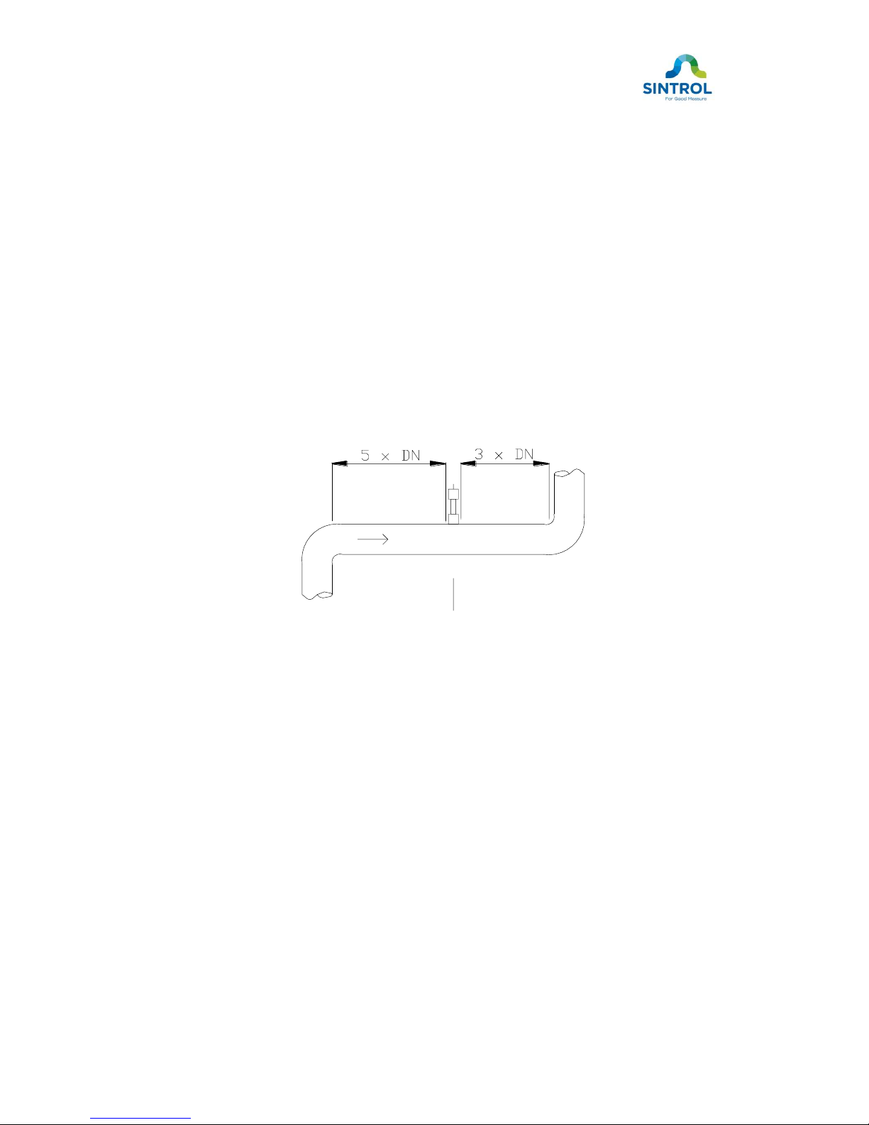
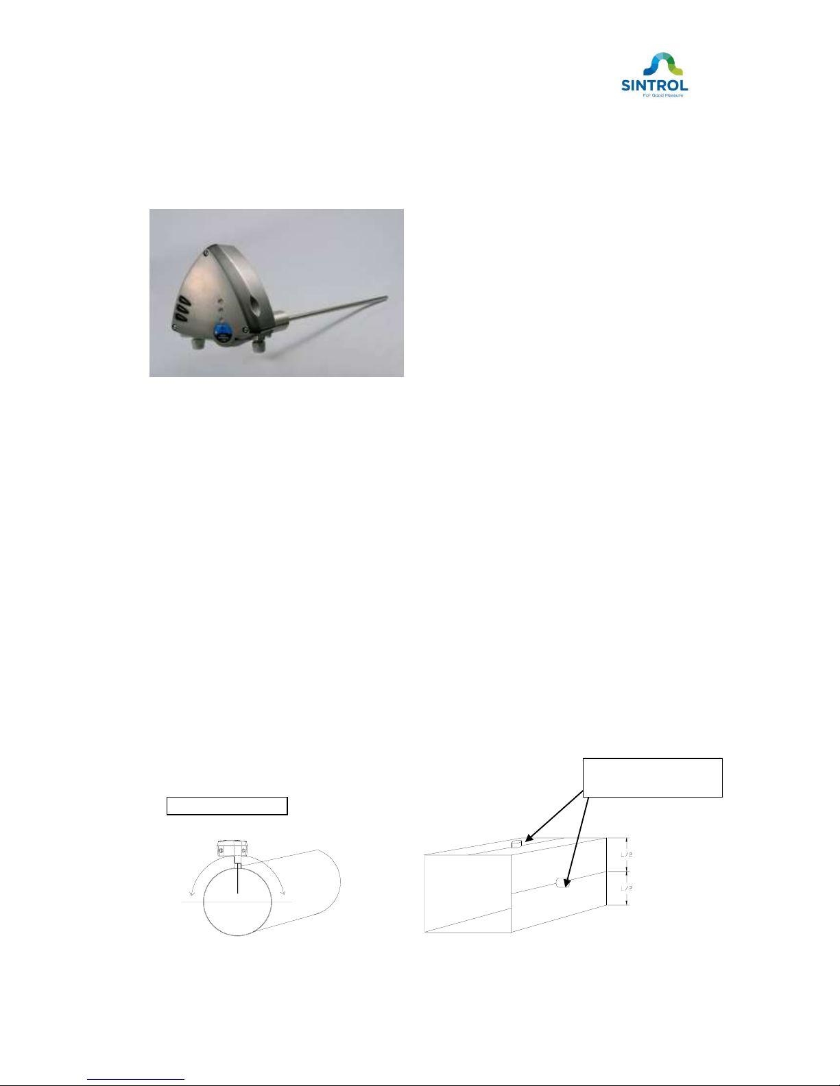
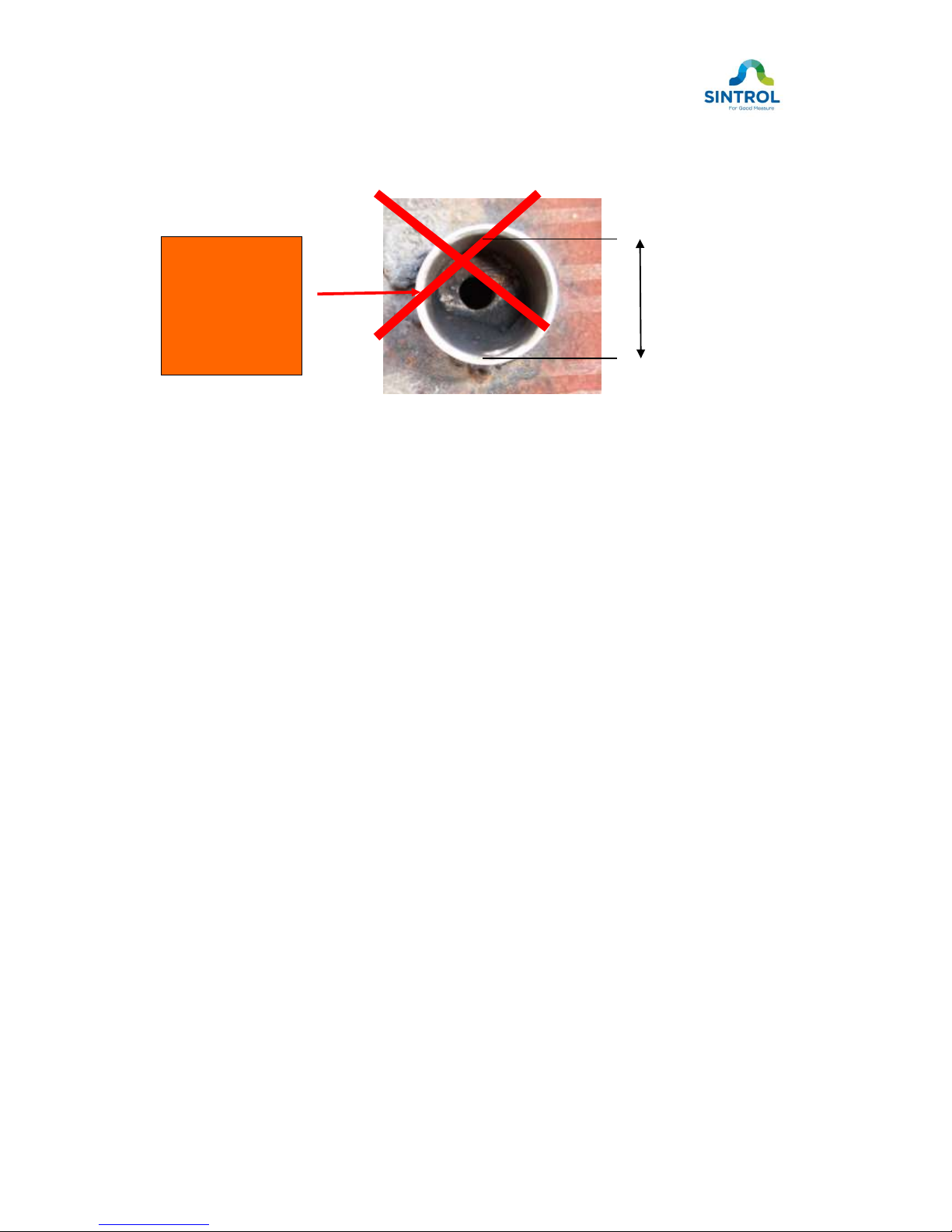
2.1 Selecting the installation location..............................................................5
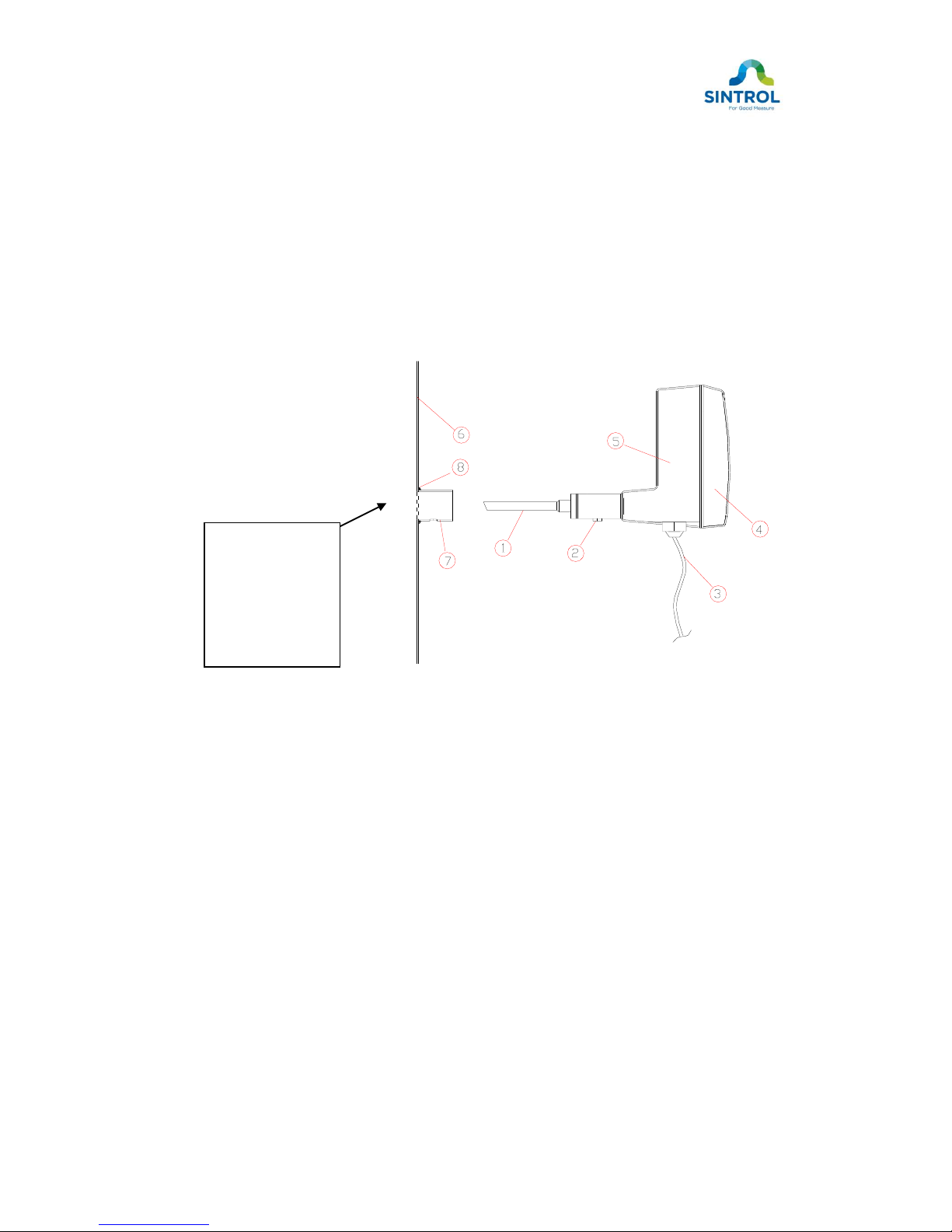
2.2 Installing the sensor....................................................................................7
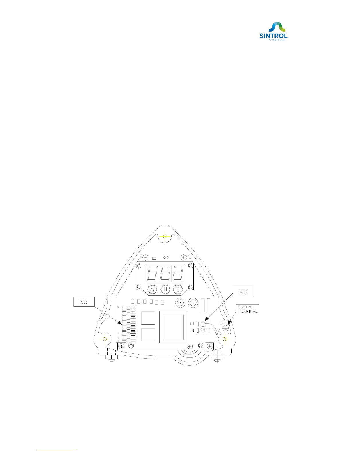
3. WIRING OF POWER AND OUTPUT CIRCUITS ....................................10
3.1 AC or DC- power connectors (X3)..........................................................10
3.2 Signal connector (X5) ...............................................................................11
4. TECHNICAL SPECIFICATION ..................................................................12
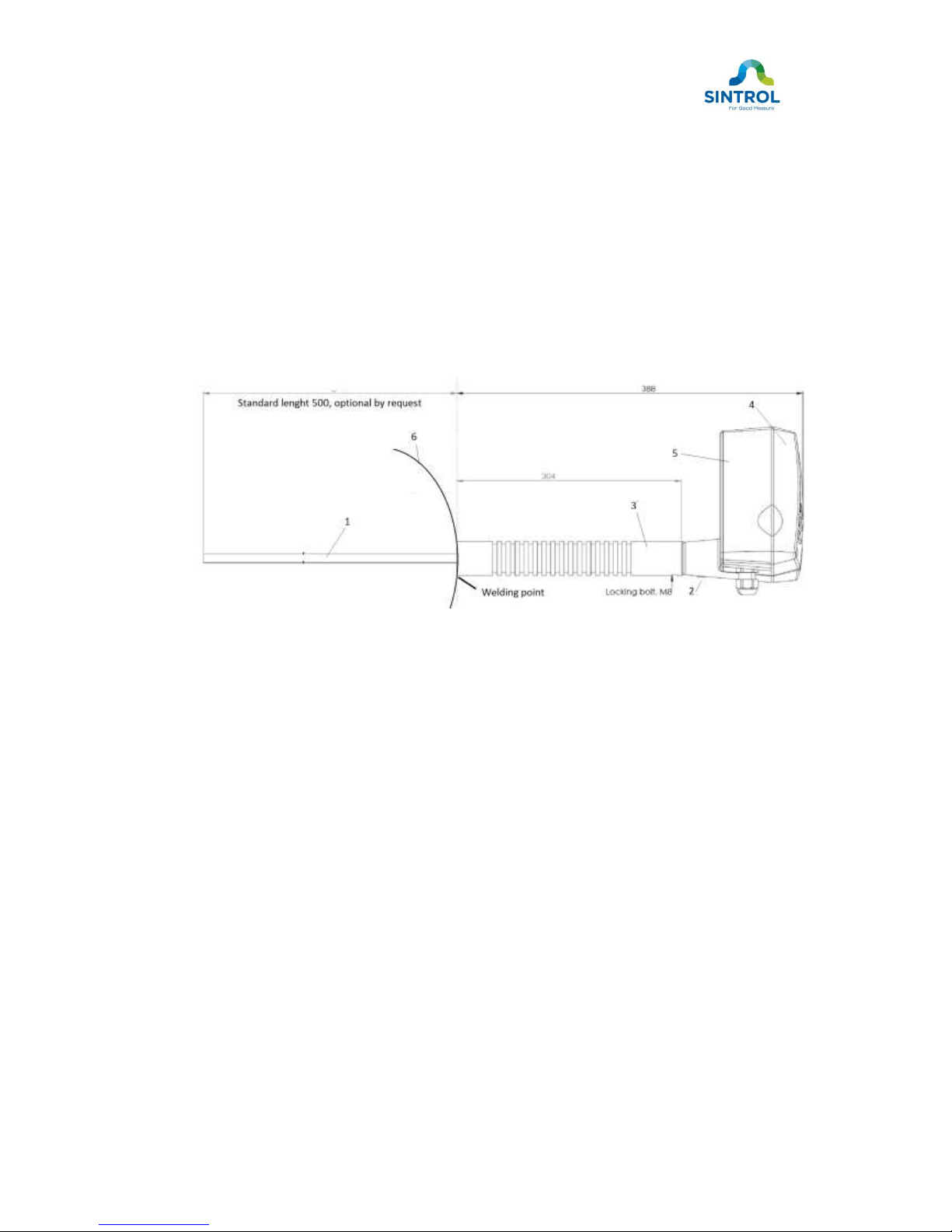
5. DIMENSIONS ................................................................................................13
6. OPERATION..................................................................................................14
6.1 Operation of the monitor ..........................................................................14
6.2 Front panel .................................................................................................15
6.3 Service mode (S305)................................................................................16
6.4 Relay connections.....................................................................................17
6.5 How to change parameter values...........................................................19
6.5.1 Parameter 1 alarm relay 1 threshold.....................................................21
6.5.2 Parameter 2 alarm relay 2 threshold.....................................................21
6.5.3 Parameter 3 Analog output zero adjustment .......................................21
6.5.4 Parameter 4 Analog output span adjustment ......................................21
6.5.5 Parameter 5 Alarm Relay delay time .....................................................21
6.5.6 Parameter 6 Analog output damping.......................................................21
6.5.7 Parameter 7 Percent level of full range during autosetup .................21
6.5.8 Parameter 8 Reference check interval (S305) .....................................22
6.5.9 Parameter 9................................................................................................22
6.5.10 Parameter 10 Output scale .....................................................................22
6.5.11 Parameter 11 Output zero adjustment ..................................................22
6.5.12 Parameter 12 PIN code (S305)..............................................................22
6.6 Automatic setup.........................................................................................23
6.7 The manual range (MR) setup (Only S304)..........................................24
6.8 Self diagnostics: Self Zero check and Span check..............................25
6.9 Calibrating to mg/m3.................................................................................26
7. MAINTENANCE ............................................................................................28
8. TROUBLESHOOTING.................................................................................28
NOTES........................................................................................................................29

3
1. INTRODUCTION
This manual describes how to install and use SINTROL digital
triboelectric dust emission monitors S304 and S305.
Sintrol shall not be held liable for any loss or damage whatsoever arising
from omissions or errors in this manual, or any misuse of the product.
1.1 Safety
Model LV requires a 115 VAC, 50/60 Hz power supply and model HV a 230
VAC, 50/60 Hz power supply. In both cases, the power supply must be
considered as potentially lethal and all suitable precautions must be taken
whenever the cover of the unit is removed.
S300 Series dust monitors are virtually maintenance free. Under no
circumstances should the user attempt to replace any components or the PC
board. If, for some reason the monitor fails to operate, contact your local
distributor or the manufacturer.
Take appropriate precautions when installing the monitor:
Unless the process conditions are known to be entirely safe,
suitable precautions must be taken before any entry is made into
the duct for installation or maintenance purposes.
The unit may be installed in ducting, containing particulate, hazardous to
health.
The particulate may be inflammable, explosive or toxic
The gas can be hot and pressurised
The S300 Series dust monitors do not have an internal circuit breaker. The
customer has to install a separate circuit breaker to the power cable to ensure
that the power can be isolated. Electrical installations must be carried out in a
manner to satisfy all applicable, local regulations.
It is essential that the unit is correctly grounded!
(see section 3.1)

4
1.2 Product overview
Models S304/S305 are linear emission monitors. They are microprocessor-
based, self-adjusting devices equipped with two alarm relays, one 4-20 mA
signal output and RS422 Serial communication.
Their main use is for dust emission monitoring. The units are compact with the
sensor and control units built into an IP65 enclosure, which has been
specifically designed for easy installation and operation. The standard model is
designed for applications at up to 2 bar and 300 °C. A high-temperature (HT)
model is available for temperatures up to 700 °C.
1.3 Principle of operation
The models S304/S305 use proven and reliable triboelectric technology where
the interaction of particles with the sensor rod causes a small electrical charge
to pass between the particulate and sensor.
It is this small electric charge that provides the signal monitored by the
electronics, the signal generated is proportional to the dust level even if
particles accumulate on the sensor. Experience has shown that this method of
monitoring dust level in gasses, offers accurate results with minimum
maintenance.

5
2. INSTALLATION
2.1 Selecting the installation location
The best location for installation of the units of the S300 Series is in a section
of duct where the particulate has an even distribution and the flow is laminar.
This is to ensure that the sensor rod comes into contact with a representative
flow of particles.
The ideal position would be in a section of duct that has no bends, valves,
dampers or other obstructions for a distance equal to at least three duct
diameters downstream or upstream (preferable 5 x duct diameter).
Figure 1. Recommended distances to duct bends
In some applications, a compromise must be made and the sensor will have to
be fitted in a position that satisfies the majority of above requirements. The
units of the S300 Series must be attached to metal ductwork so that they will
be electrically shielded from interference and be provided with a ground
reference. For non-metal ducts, a section of the duct, approximately five
diameters in length, should be covered with a metal foil or fine-mesh outside of
the duct.
The units must not be installed in direct sunlight or in areas where the ambient
temperature is above 45oC. Please contact your local distributor or Sintrol if
you require further advice.

6
Figure 2. S305 Emission Monitor
The unit shall be installed in a position, where the gas flow passes the sensor
rod in a 90angel.
In round cross-section ducts, the unit can be installed in any position above the
horizontal axis (between 9 o’clock and 3 o’clock).
For square cross-section ducts, the unit must be positioned in the middle of the
top or in the middle of one of the sides. In all cases, the tip of the sensor rod
must extend at least 1/3 of the diameter of the duct. Depending on the dust
concentration, the probe length could vary from 1/3 to 2/3 of the duct diameter.
As a rule of thumb: the lower the dust concentration the longer the probe.
If possible the unit shall be installed in a position where the duct pressure is
negative.
If installed downstream an electrostatic precipitator (ESP), the distance from
the ESP should be at least 20 m. Although the sensor (lengths less than 1m)
is not affected by vibration, very high vibration levels should be avoided.
Figure 2a. Round cross-section duct Figure 2b. Square cross-section duct
mounting socket in the
middle of the side or top
above horizontal axis

7
2.2 Installing the sensor
Once the location of the unit has been selected, the mounting socket must be
welded to the pipe or duct. To do this, first cut a hole in the duct slightly
larger than the OD of the mounting socket, 38 mm. The socket must be
perpendicular to the flow in the duct. Make sure the socket is in the right
position and make an airtight welding. After welding the socket in position,
insert the sensor.
Figure 3a. Sensor installation
1. Probe 5. Enclosure
2. Fixing screw 6. Duct wall
3. Cables (mains and signals) 7. Socket
4. Cover 8. Weld
Diameter of the
hole to the stack
must be
minimum Ø 38
mm. to avoid the
sensor probe
contact to the
duct wall.

8
When installing HT or HT/MP sensor it is important to take care that the
ambient temperature will not increase above 45 degree. The electronics
inside of enclosure is sensitive for temperature.
To do the installation, first cut a hole in the duct slightly larger than the OD
of the mounting socket, 38 mm (HT ) 45 mm (HT/MP). The socket must be
perpendicular to the flow in the duct. Make sure the socket is in the right
position and make an airtight welding. After welding the socket in position,
insert the HT or HT/MP sensor.
Figure 3b. Monitor installation with HT or HT/MP sensor
1. Probe 5. Enclosure
2. Fixing screw 6. Duct
3. Cooling extender
4. Cover

9
38
mm
WRONG SOCKET INSTALLATION
Figure 4. Wrong socket installation,
THE DIAMETER OF THE HOLE MUST BE MINIMUM 38 MM
IMPORTANT
!!
Hole diameter
must be at least
38 mm

10
3. WIRING OF POWER AND OUTPUT CIRCUITS
3.1 AC or DC- power connectors (X3)
Voltage: 230 VAC +/- 20 V or 115VAC +/- 10V or 24 VDC
Frequency: 45 Hz … 65 Hz (AC models)
Power cable: 3 x 1,5 mm2
Connect a 115/230 VAC power supply or a 24 VDC power supply to connector
X3 (see Figure 5). Push the connector lever until the connector slot jaw opens.
Insert the power supply lead, then release the lever. Attach the ground wire to
the GND screw.
AC1 - power input (- terminal in 24 VDC model)
AC2 + power input (+ terminal in 24 VDC model)
GND Protective earth terminal.
Figure 5. Wiring
Ce manuel convient aux modèles suivants
1
Table des matières


