Sineoji PL500EW Manuel utilisateur

User Manual
PL500EW
500Mbps HomePlug AV 2-Port Wireless Range Extender

Safety
CE
This equipment is in compliance with the requirements of the following regulations: CE Mark, 89/336/EEC

Features
HomePlug Features
Power voltage range is 100 to 240 V AC 50-60Hz.
Support the HomePlug AV protocol and the IEEE1901 protocol.
PLC physical link rate is up to 500Mbpsbps.
Support the following modulation schemes: OFDM QAM 4096/1024/256/64/16/8, QPSK, BPSK, and ROBO.
Support 128-bit AES link encryption and user NMK authentication, for providing secure power line communication.
Support windowed OFDM with noise mitigation based on patented line synchronization technique, for improving data
integrity in noisy conditions.
Support channel self-adaptation and channel estimation for maximizing real-time throughput.
Support priority-based CSMA/CA channel access scheme for maximizing efficiency and throughput.
Support four-level QoS.
Support ToS and CoS packet classifications.
Support IGMP multicast management session.
Wireless Features
Support IEEE802.11b, IEEE802.11g, IEEE802.11n, IEEE802.3, IEEE802.3u, IEEE802.11i and IEEE802.11e.
Support 2T2R mode. Transmission data rate is up to 300Mbps.
Support WEP and WPA for secure data transmission.
Support DHCP server.
Support restoring factory default settings.
Support the following wireless security modes: WEP, WPA-PSK, WPA2-PSK, and WPA/WPA2-PSK
Support system status display.
Support system log.
1 HomePlug Powerline
HomePlug Powerline is an excellent solution that can be used to extend your network. In the home or small office building,
use HomePlug Ethernet Bridges to link multiple locations without the need to run long Ethernet cables. Combined with a
broadband DSL/Cable connection, every room with electrical power outlets will have easy access to high-speed Internet con-
nection. With the HomePlug AV speed of up to 500Mbps, this easy-to-setup solution can provide fast streaming HD movies,
online multiplayer games, and other data intensive activities for today’s HD Entertainment Center demand.
1.1 Introduction
Each HomePlug AV Ethernet Bridge allows you to connect one device that has an Ethernet port to a Powerline network. In
operation, the HomePlug AV Ethernet Bridge is completely transparent, and simply passes data between the Ethernet port
and the Powerline network. Any Ethernet-enabled device may be connected to the HomePlug AV Ethernet Bridge’s Ethernet
port.
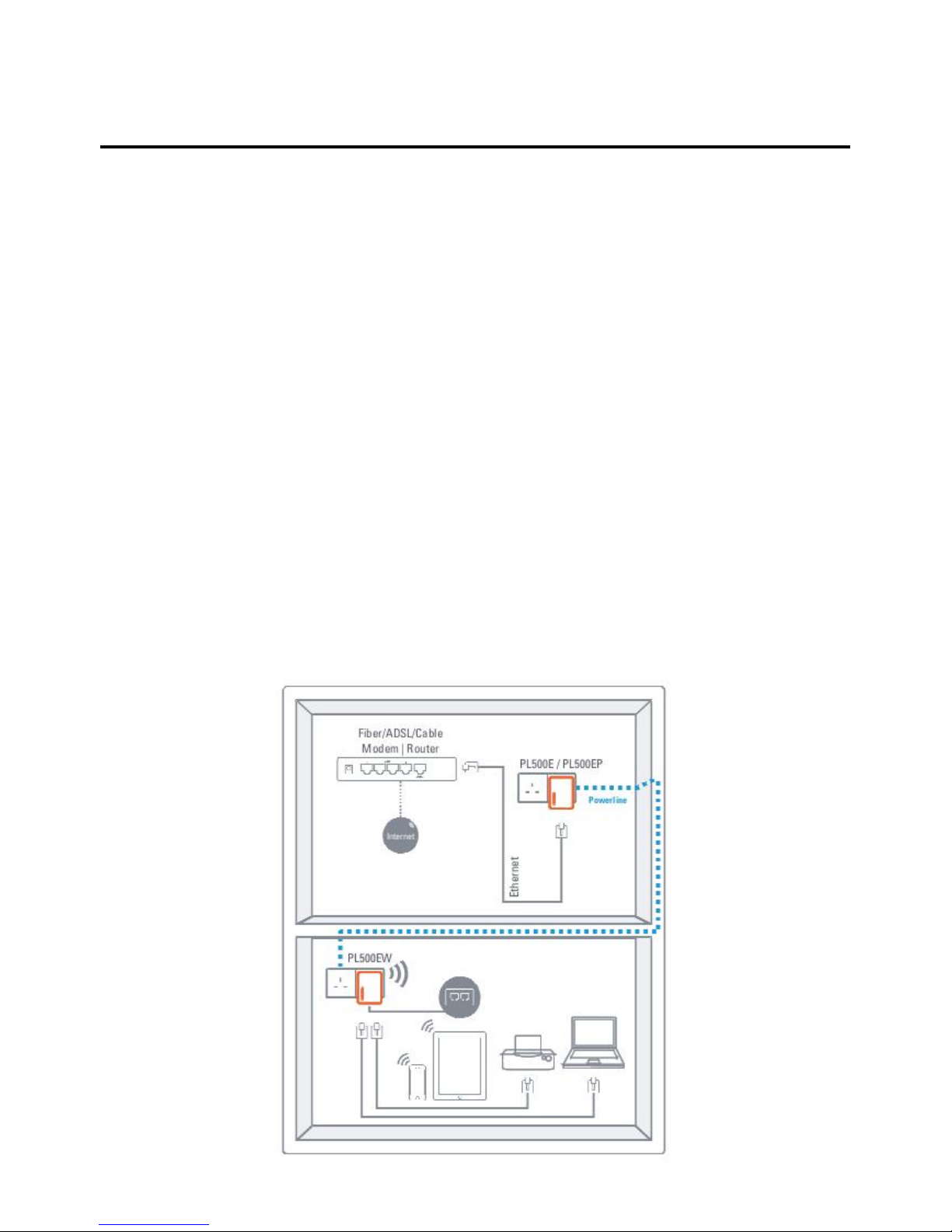
1.2 System Diagram
Add high-speed Internet access to any room in your home with this HomePlug AV Ethernet Bridge. You can stream HD
movies and music, play online multi-player games and much more.
Note: HomePlug AV Ethernet Bridge needs to pair with at least one other HomePlug AV compatible device such as this one in
order to create a working system.
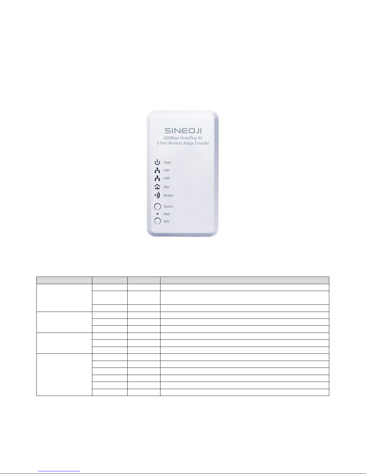
1.3 Casing Details
Front Casing
Status Lights
The following table describes the status of LED indicators on the front panel:
LED Indicator
Color
Status
Description
Power
Green
On
System runs normally.
Green Blink System is resetting.
System is in the process of password synchronization.
-
Off
Device is powered off or system is down.
LAN1
Green
On
Connection via the LAN1 interface succeeds.
Green
Blink
Data is being transmitted via the LAN1 interface.
-
Off
No connection is established via the LAN1 interface.
LAN2
Green
On
Connection via the LAN2 interface succeeds
Green
Blink
Data is being transmitted via the LAN2 interface.
-
Off
No connection is established via the LAN2 interface.
Data
Green
On
HomePlug transmission rate equals to or is greater than 40Mbps.
Orange
On
HomePlug transmission rate is between 20Mbps and 40Mbps.
Red
On
HomePlug transmission rate is smaller than or equals to 20Mbps.
-
Off
Device is not connected to the power line network.
Green
Blink
Wireless data is being transmitted.
Orange
Blink
WPS negotiation is in progress and wireless data is being transmitted.
The following table describes pushbuttons on the front panel:
Button
Description
Security
It is used to set the status of the device members.
Press and hold the Security pushbutton for more than 10 seconds to exit the current
network and generate a random password of network member.
Press and hold the Security pushbutton for less than 3 seconds, and then the HomePlug
becomes a member of the existing AVLN.
Reset Press the Reset pushbutton for more than 3 seconds and then release it. System
restores the factory default settings.
WPS
It has the following functions:
Press the WPS pushbutton for less than 3 seconds to enable the negotiation of PBC
mode.
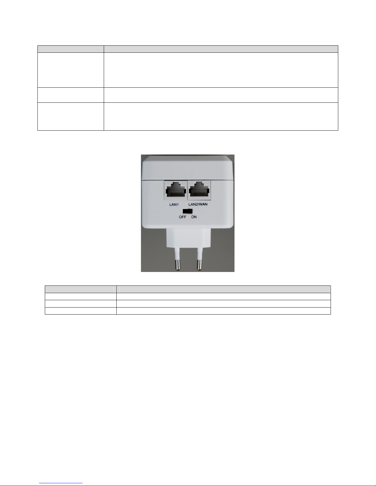
Interface and Switch Description
The following table describes interfaces and switch on the HomePlug
Interface
Description
LAN1
RJ45 LAN interface, for connecting a hub, switch, or computer on a LAN.
LAN2
RJ45 LAN interface, for connecting a hub, switch, or computer on a LAN.
OFF ON
Turn on or turn off the device.
1.4 Initial Setup
HomePlug is a plug and play device; user is able to plug and play without any complex configuration and settings. You can use
HomePlug AV to connect networkable devices like computers and game consoles directly to each other. You can also con-
nect devices like a computer or Blu-ray Disc™ player to a router or modem for Internet access.
Connect the HomePlug AV Ethernet Bridge to a Computer or Modem/Router
1. Plug one end of the Ethernet Cable into the Ethernet Port on the bottom of the HomePlug AV Ethernet Bridge
2. Plug the HomePlug AV Ethernet Bridge into a AC Wall Power Outlet near the device you want to connect
Warning: Do not plug this HomePlug AV Ethernet Bridge into a powerstrip that has surge protection. Doing so will de-
grade Powerline performance. For best performance, plug all HomePlug AV Ethernet Bridges directly into a wall outlet.
3. For connecting to a computer: Plug the other end of the Ethernet Cable into an OPEN Ethernet Port located on your com-
puter.
4. For connecting to a Modem or Router for Internet access: Plug the other end of the Ethernet Cable into an OPEN Ethernet
Port on your Modem or Router.
5. Make sure that the Data LED light on each HomePlug AV Ethernet Bridge turns solid green.
6. Your HomePlug AV Ethernet Bridges are now connected forming a HomePlug AV network.
2 Individual HomePlug AV Network Setup (Optional)
All HomePlug AV Ethernet Bridges ship with a default security key so they will automatically link to all other HomePlug AV
Ethernet Bridges sharing the same electrical lines. If there are other HomePlug AV Ethernet Bridges in the building (such as in
an office or apartment building), you may want to create your own individual HomePlug AV network group so other
HomePlug AV Ethernet Bridges cannot connect to your network.
This section describes how to use the Security button for configuration in the following situations:
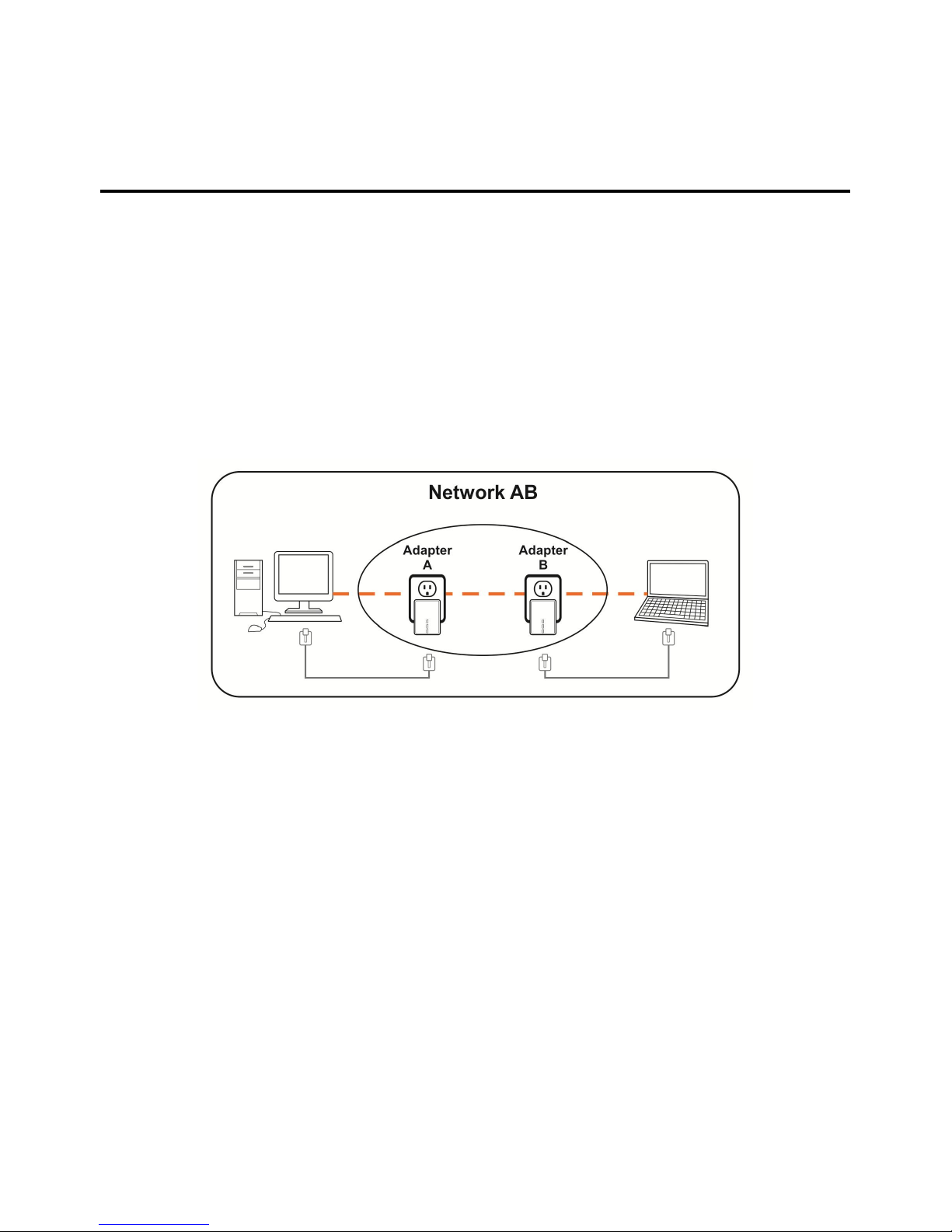
2.1 Creating a new individual HomePlug AV network (Network AB)
Two unassociated Bridges (Bridge A and Bridge B) are forming a new network—Network AB
The procedure is as follows:
1. Press and hold the Security button on Bridge A for no more than 10 seconds. Must release after 10 seconds. Once re-
leased, the Power light will flash.
The password to Bridge A has just been erased and random security key has been generated. It must now be linked to
your network to adopt the new network security key.
2. Press and hold the security button on Bridge B for 10 seconds and release it when the Power light flashes. The password
to Bridge B has just been erased and random security key has been generated. It must now be linked to your network to
adopt the new network security key.
3. Currently, Bridge A and Bridge B are not networked
4. Press and hold the Security button on Bridge A for 1~3 seconds then release.
5. The Power light on Bridge A starts to flash.
6. Within 120 seconds after the Power light on Bridge A starts to flash, press and hold the Security button on Bridge B for
1~3 seconds then release.
7. Both Bridge A and Bridge B are now networked together.
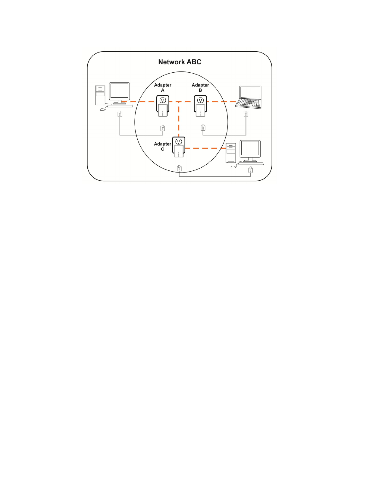
2.2 Adding Bridge C to existing Network AB (Network ABC)
One unassociated Bridge C is added to an existing Network AB.
The procedure is as follows:
8. Press and hold the Security button on Bridge C for no more than 10 seconds. Must release after 10 seconds. Once re-
leased, the Power light will flash.
The password to Bridge C has just been erased and random security key has been generated. It must now be linked to
your network to adopt the new network security key.
9. Press and hold the security button on Bridge A for 1~3 seconds. The Power light on Bridge A starts to flash.
10. Within 120 seconds after the Power light on Bridge A starts to flash, press and hold the security button on Bridge C for
1~3 seconds then release.
11. Bridge A, Bridge B and Bridge C are now networked to each other.
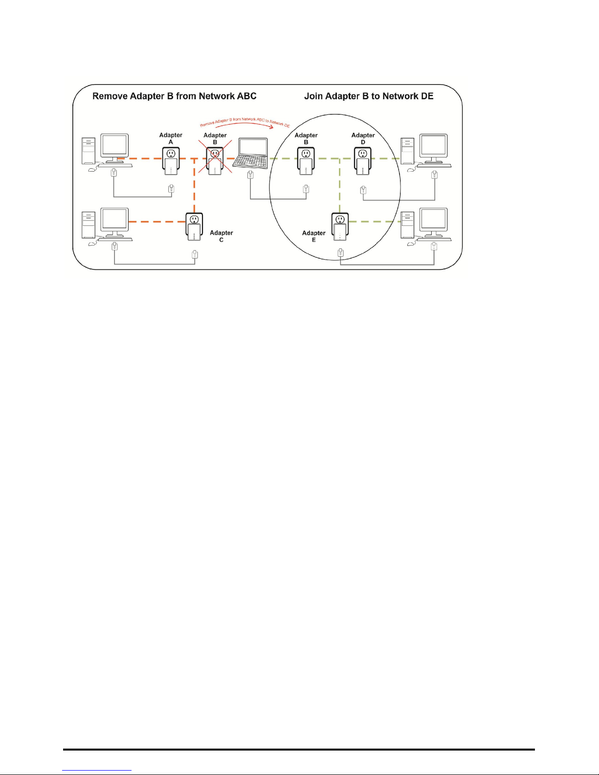
2.3 Removing Bridge B from Bridge A & C Network and join with Bridge D & E
(Network BDE)
The procedure is as follows:
1. Press and hold the Security button on Bridge B for no more than 10 seconds. Must release after 10 seconds. Once re-
leased, the Power light will flash.
The password to Bridge B has just been erased and removes itself from Bridge A & C.
2. Press and hold the Security button on Bridge D for 1~3 seconds.
3. Within 120 seconds after the Power light on Bridge D starts to flash, press and hold the Security button on Bridge B for
1~3 seconds then release.
4. Bridge B and Bridge D are now connected to each other, which in turn becomes part of Network BDE.
2.4 Setting Up the Wireless Extender
By default, the wireless parameters has been pre-configured as follows:
Wireless SSID : Sineoji_PL500EW
Wireless password : 1234567890
Default IP address : 192.168.33.1
To connect to the Wireless Extender, select the wireless search utility in Windows and locate “Sineoji_Pl500EW”.
You will be prompted to enter the password. Enter “1234567890” and the wireless connectivity has been setup
successfully.
2.5 Changing the Wireless Password
1. Plug the HomePlug directly on the power socket.
2. Connect an Ethernet cable to LAN 1 of the HomePlug and the other end to the Ethernet port of the Desktop PC or Note-
book.
3. Right mouse click on the “NETWORK” icon of your Windows Desktop
4. Select “OPEN NETWORK AND SHARING CENTRE”
5. Select “CHANGE ADAPTER SETTINGS”
6. Right mouse click on the desired LAN and select “PROPERTIES”.
7. Double click on “INTERNET PROTOCOL VERSION 4(TCP/IPv4)
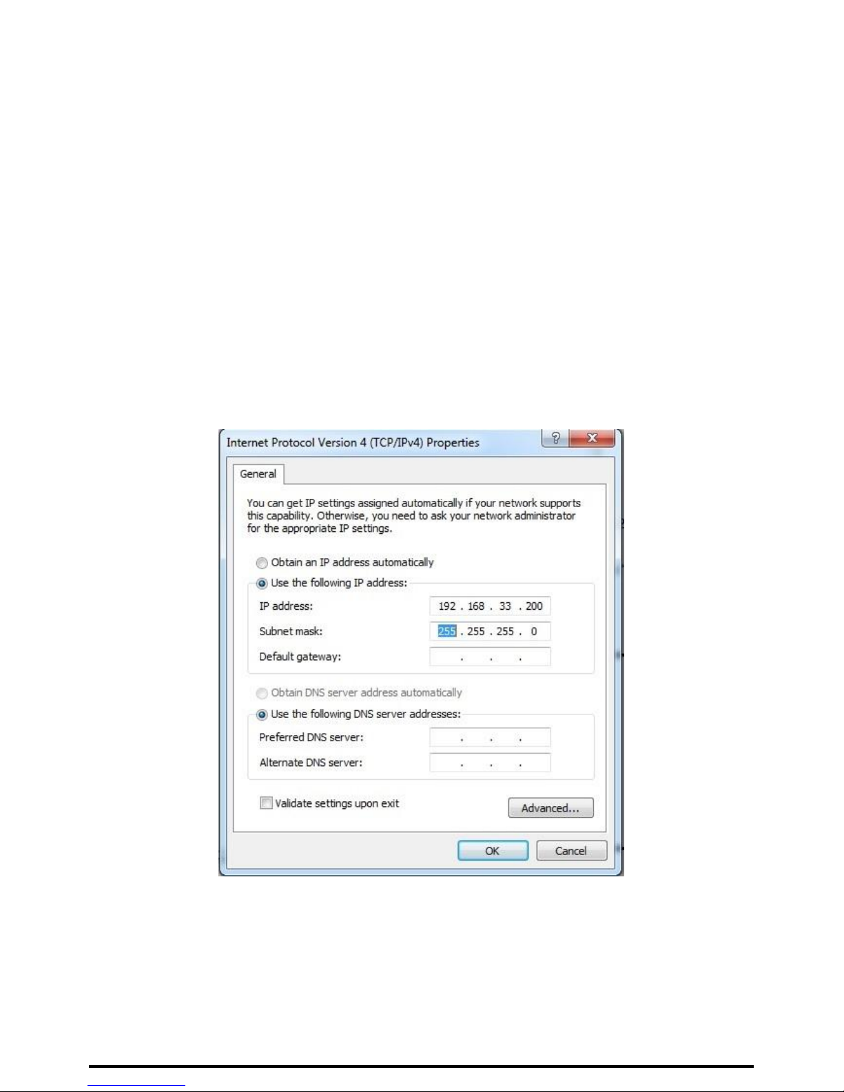
8. Select “USE THE FOLLOWING ADDRESS”
9. Enter the following:
IP address: 192.168.33.X (where X will be any numerical value from 10 – 254)
Subnet Mask: 255.255.255.0
10. Select OK and proceed to the Browser and enter the following IP address “192.168.33.1) to access the setup page. Enter
“admin” as the password to access the setup.
11. Proceed to “WIRELESS SETUP” and select “WIRELESS BASIC”. Enter the passphrase you wish to change the default
password. Click “APPLY”.
Table des matières


