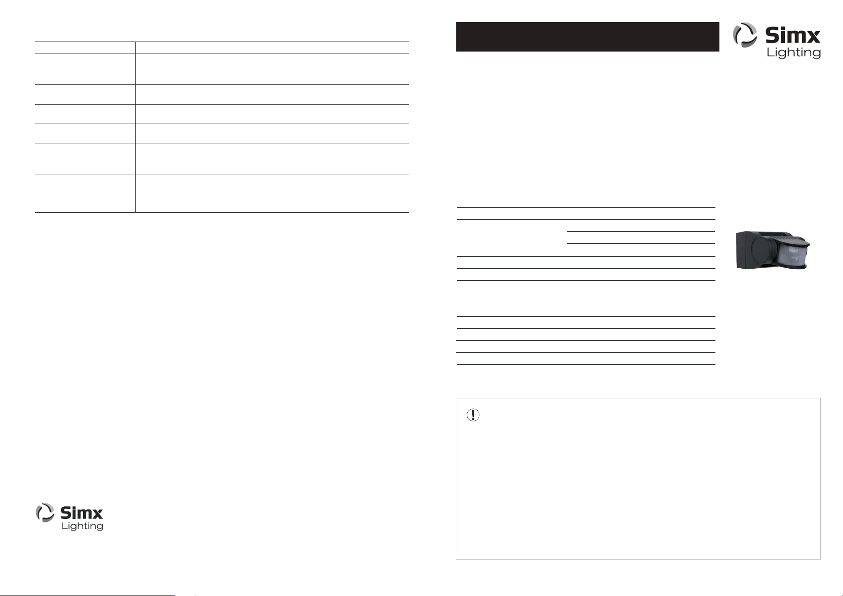
CONFIGURATION
WALK TESTING PROCEDURE
Adjust the sensor to point in the desired direction. Set the adjustment controls on the underside of the
unit to the following to enable daytime operation for walk testing:
TIME - Fully anti-clockwiseLUX - Fully clockwise
SETTING UP FOR AUTOMATIC OPERATION
MANUAL OVERRIDE MODE
BEFORE YOU START
Please read all the instructions prior to installation.
INSTALLATION
We strongly recommend this light fitting is installed by a registered electrician
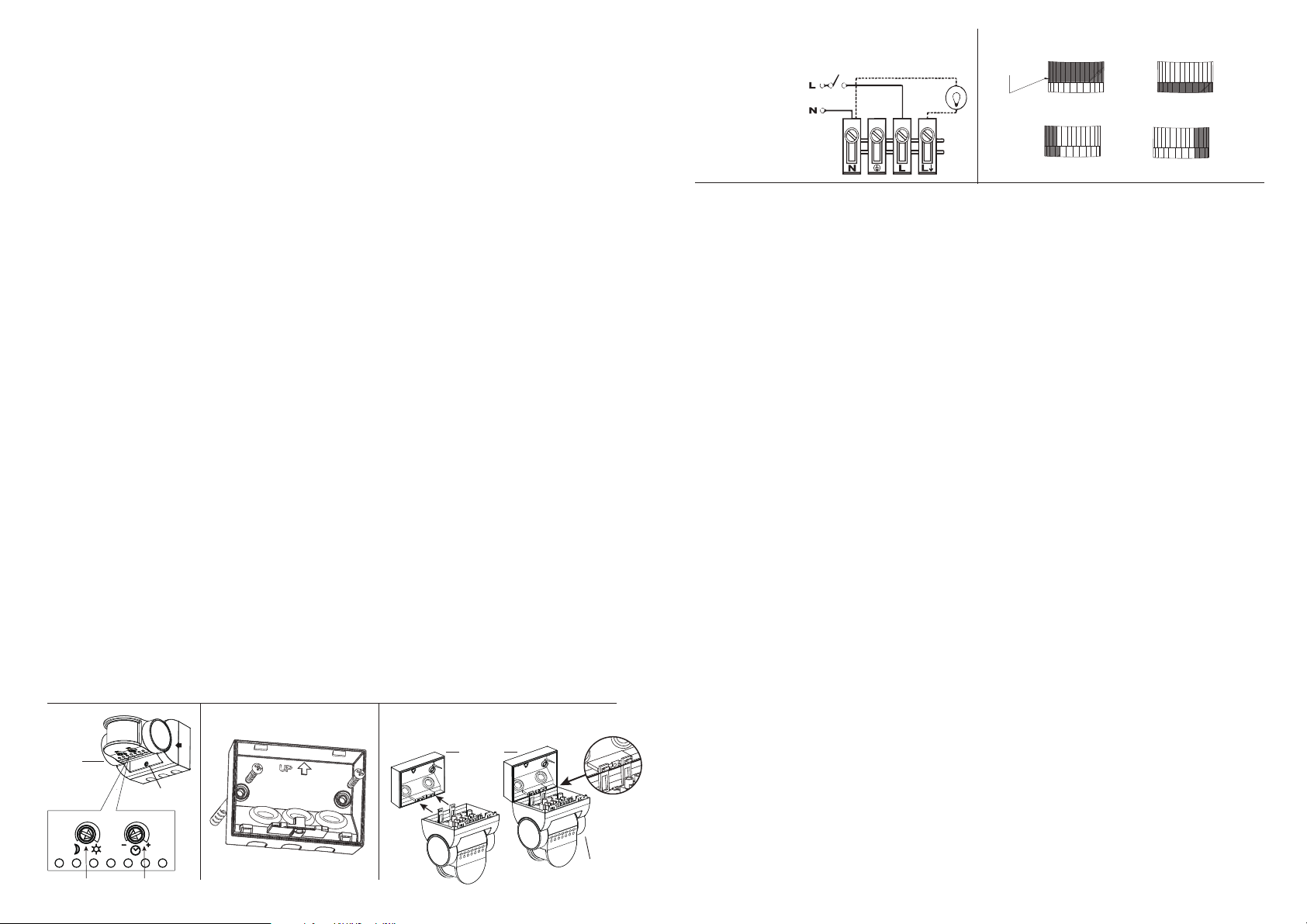
Fig. 5Fig. 4 WIRING DIAGRAM
N
L
= NEUTRAL (Blue)
=LIVE (Brown)
Isolating Switch
Load
Restrict long detection Restrict short detection
Restrict RHS detection Restrict LHS detection
Lens Mask
Fig. 2 3.giF1.giF
Wall Plate
Main Body
Hang main body on wiring box for easier wiring
Fixing Screw
Settings
The light can be switched on for longer periods by use of the Manual Override mode. This can be activated
at night by using the internal wall switch or circuit breaker. Switch the internal wall switch/circuit breaker
once (off/on) within 1.5 seconds. The unit will now illuminate continuously for 6 hours and will then revert
back into Auto mode. Alternatively manually flick the internal wall switch/circuit breaker once (off/on) within
1.5 seconds, then the unit will return to Auto mode.
The TIME setting controls how long the lighting remains illuminated following activation & after all motion
ceases. The minimum time (fully anti-clockwise) is approx. 5 seconds, whilst the maximum time
(fully clockwise) is approx. 15 minutes. Set the control to the desired setting between these limits.
The LUX control determines the level of darkness required for the unit to start operating. To operate the
sensor in lighter conditions, adjust the LUX control clockwise. To operate the sensor in darker conditions,
adjust the dusk control anti-clockwise. Wait for at least 1 minute between adjustments.
An easy way to set the sensor to your desired light level is to set the dusk control fully anti-clockwise,
then wait until the ambient light level reaches the level of darkness at which you wish the lamp to become
operative. The unit may trigger when the dusk control is adjusted, it will settle into normal sensing mode
after 1 minute of inactivity. SLOWLY rotate the control in a clockwise direction until a point is reached
where the lamp illuminates. Leave the control set at this point.
• Switch off the power supply before commencing any electrical work.
• An internal switch should be installed to switch the power to the unit ON & OFF. This allows the sensor
to be easily switched off when not required or for maintenance purposes, and for activating manual override.
• Unscrew the wiring box fixing screw (Fig. 1). This screw is captive, do not fully remove,
remove the rear cover.
• Using the wiring box as a template, mark the position of the fitting holes. (Fig. 2) Drill the holes.
Care should be taken to avoid drilling or screwing into concealed electrical wiring/plumbing.
Insert the wall plugs if required for solid walls.
• Pierce the power cable entry grommet on the wiring box and slowly draw the power cable through
the entry hole. A 3-core round flexible cable of 1.0 - 1.5mm² gauge is recommended.
• Attach the mounting plate to the wall using screws provided. Do not overtighten the mounting screws.
• This unit features an installation aid. Simply hang the sensor onto the wall plate by use of the clip
arrangement on bottom edge of wall plate (fig 3). This leaves your hands free to install the incoming
cables with ease. Connect the incoming and outgoing cables as follows shown in (fig 4)
• Reattach and screw securely the cover to the base. Ensure cables are not pinched in closing the unit.
• Reconnect mains power. Test circuit and setup PIR settings (see configuration section).
• The Smart Sense PIR sensor should be wired to its own switch. Do not interconnect with other sensor
types on the same switch. Do not install during wet weather.
• Lighting loads connected directly must not exceed maximum listed in Technical Specifications
• To achieve best results, please consider the following points:
• If you intend to use this product with compact fluorescent energy saving lamps,
we suggest the TIME setting is set to a minimum of 3 minutes.
• Before selecting a place to install your Smart Sense PIR sensor, note that movement across
the scan area is more effective than movement directly toward or away from the sensor.
The best all-round coverage is achieved with the unit mounted 2.5 metres above the ground.
• To avoid false triggering, direct the sensor away from heat sources such as barbecues, air con,
flue vents etc or reflective surfaces such as smooth white walls, swimming pools, etc.
This sensor may operate abnormally in extreme weather conditions. This is not a fault and should resume
normal operation when weather settles.
• To reduce the risk of light pollution, install and position any lights controlled by this sensor carefully to
ensure that the light emitted does not encroach onto neighbouring properties. The lamp will switch on for a "warm-up" period for 1 minute. Remain outside the detection area during the
warm-up period. Walk across the detection area approx 5 metres from the unit. As you cross a detection
"zone" the lamp will illuminate. Stand still until the lamp extinguishes (approx. 5 secs) then start moving
again. As you cross each "zone" the lamp will illuminate.
Repeat the above, walking at various distances and angles to the unit. This will help you to establish the
detection pattern. If the detection area is too small for your requirements, angle the sensor head up to
increase the coverage distance. Angling the head downwards will reduce the range should a smaller
coverage area be required.
Time
Night/Day
MASKING THE SENSOR LENS
To restrict the sensor coverage, preventing detection in unwanted areas, mask the sensor lens using
the masks (included in kit). For your information, the top section of the lens covers long range detection,
the bottom covers short range. Cut lens mask to suit, and bend mask outwards when fitting so it clicks
in securely (Fig. 5).