Trademarks and registered trademarks of General Dynamics Ordnance and Tactical Systems-Canada Inc. are denoted by TM and ®respectively.
www.simunition.com
© 2018 General Dynamics-OTS Canada Page 5 of 13
8972121_Cleaning process_rev02
3.
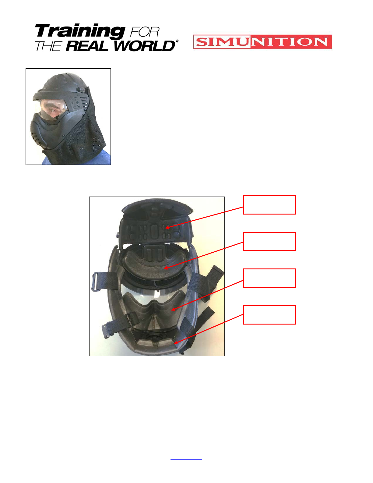
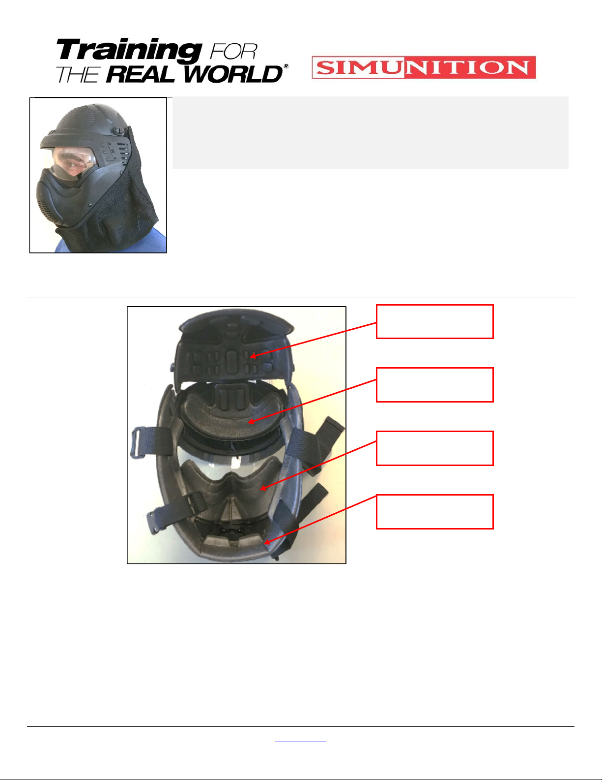
Re-install the Anti-Soap Baffle by
inserting the posts in the rectangular
opening (4) (see fig. 23) Make sure
that the FX 9002 logo wording which
is embossed is properly oriented,
then
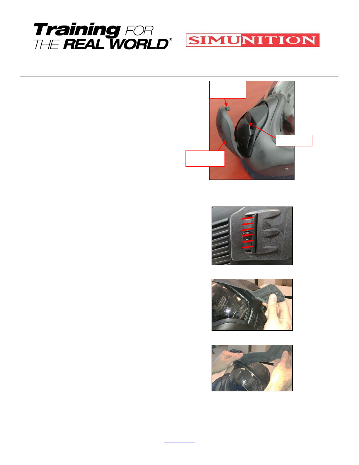
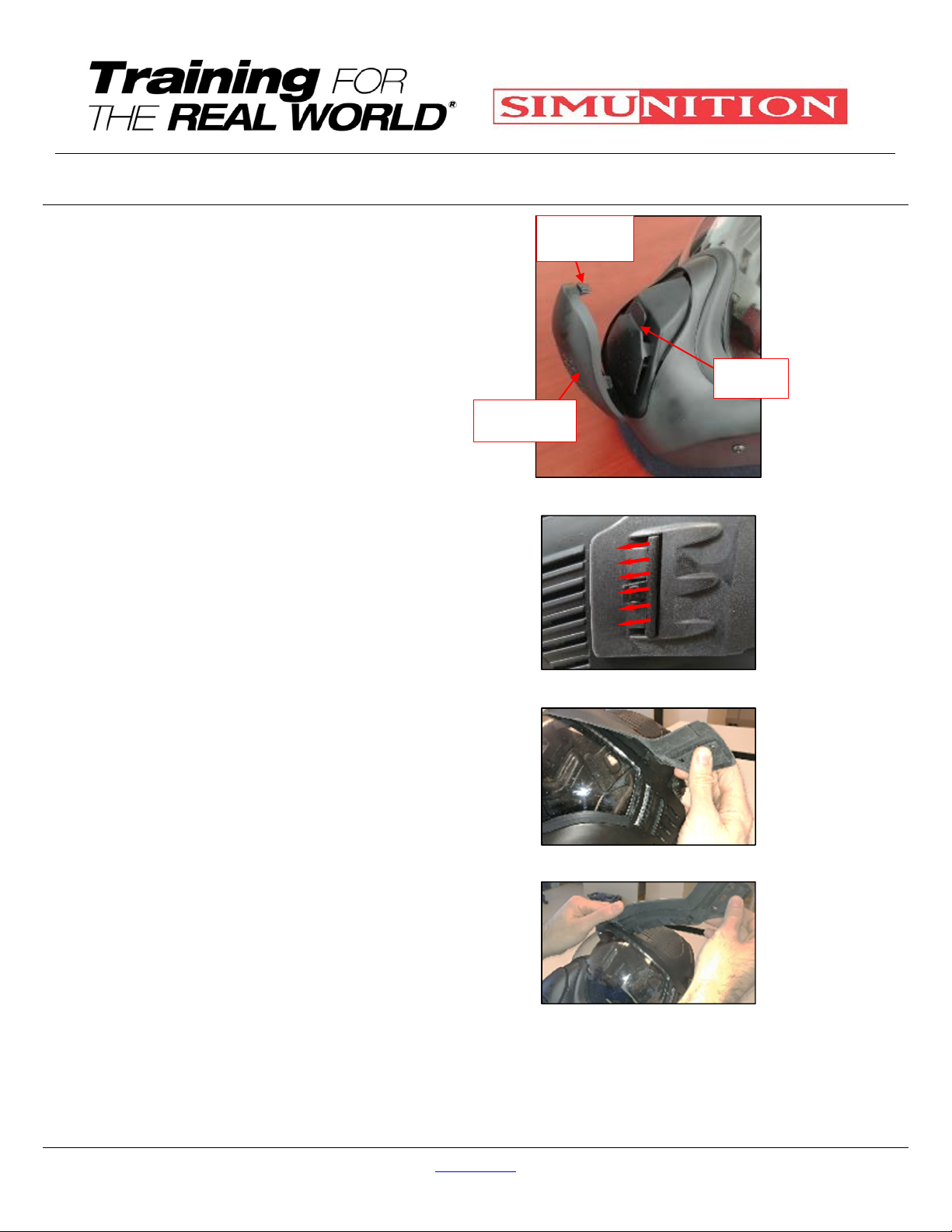
4.
Re-install the Cover Valve Outlet by
inserting the lower post (1) into the
lowered opening (Fig. 24) and then,
flip the Cover Valve Outlet and insert
the top Flap into the opening and
snap it by pressing firmly. You
should hear a click noise which will
indicate that Cover Valve Outlet is
properly installed (Fig 25).
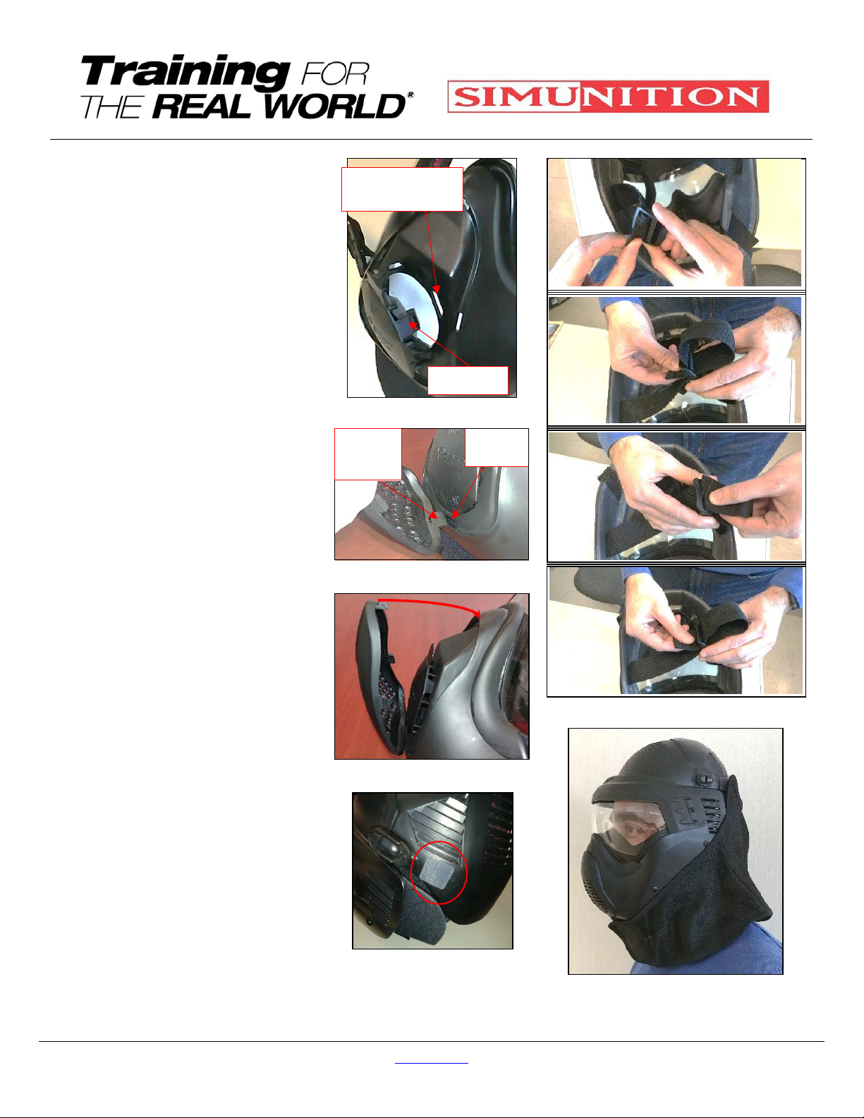
5.
Re-install the Wing foam part by
inserting at first the upper head strap
ends through the foam opening (2)
which are located at the end of both
sides of the Starship, then, thread
the loosen installation strap end
through the strap buckle openings as
showed in figure 27.
6.
Then insert the lower head strap
ends through the foam openings (2)
which are located in the lower chin
portion of the Wing and leave it
unbuckle
7.
Re-install the Crow, Wings, Starship
and Nasal foams (see fig. 18)
8.
Re-install the Back Head protection
by starting to install at first the upper
Velcro hooks (2) (square shape)
facing the Velcro Loop (2) which are
located on the back of the hard FX®
9002 Helmet, Head Protector’s
Shell (see fig. 26) and to conclude,
9.
Attach the back head protection
hood to the FX®9002 Helmet,
Head Protector fastening Velcro®
loop and make sure the back head
protection hood overlaps the
peripheral edge of the FX®9002
Helmet, Head Protector shell (Fig.
28).
Fig. 23 – Rectangular vs posts
Fig. 24 – Lower post
Fig. 25 – Opening
Fig. 26 – Velcro hook
Fig 27 – Strap buckle installation
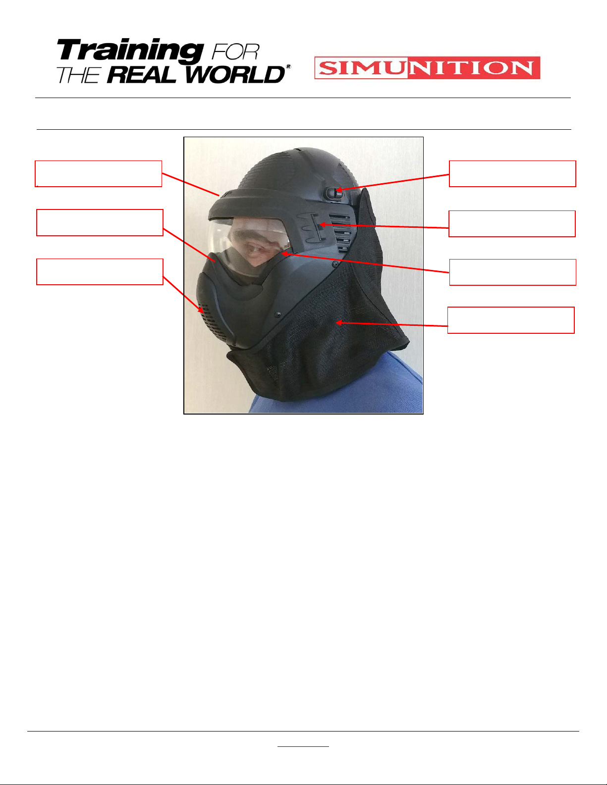
Fig. 28 – FX®9002 Helmet, Head
Protector’s textile cover
Posts(4)
Rectangular
opening(4)
CoverValve
Outlet
Lowerpost
Lower
opening