SIMREX DataMover SS Synchronous Manuel utilisateur
SIMREX Corporation
DataMover SS Synchronous
Instruction Manual
Synchronous Data Radio
Firmware Release 0.99.9
SIMREX MAN.DMSS-SYNC, Rev 1.0
AUGUST 2009
SIMREX Corporation
Your Trusted Wireless Solution Provider
www.simrex.com


DataMover SS 900 Synchronous
rev 1.0
SIMREX Corporation
1 of 13
Introduction
The
SIMREX Corporation
DataMover SS-900-SYNC is a
wireless radio device that is used in any data application
that uses equipment that communicates with
synchronous RS-232 in SDLC format.
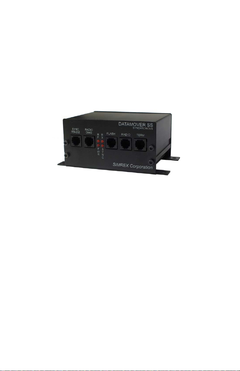
There are five (5) RJ-12 connectors on the front of the
unit:
1. SYNC RS-232 – The port the connected
synchronous device attaches to.
2. TERMINAL (6-pin RJ-12) – Used for
configuring the DM SS-900-SYNC radio.
3. RADIO DIAG (6-pin RJ-12) – This port is
used for configuring the Radio system.
4. FLASH UPDATE (6-pin RJ-12) – firmware
upgrade using proprietary flash upgrade
cable (optional).
5. RADIO - This connector is not used in the
field. It is for factory use only.

DataMover SS 900 Synchronous
rev 1.0
SIMREX Corporation
2 of 13
LED Indicators
PWR LED Indicates voltage at the output of the
internal 5V regulator.
RF LED On a unit configured as a radio master,
this LED should always be on. It shows
that the master is transmitting. On a
unit configured as a remote radio, the
RF LED shows that the remote has
associated with the master and is
active on the radio network.
RX LED This LED flashes on, then off, for each
completed message received over the
radio link.
SYNC LED This LED flashes on, then off, for each
completed message received on the
synchronous serial port.
The RX & SYNC LED’s show when data is received, only
not transmitted. In this system, it is assumed that when
a complete message is received over either transport
method, it is retransmitted over the other transport.
DataMover SS 900 Synchronous
rev 1.0
SIMREX Corporation
3 of 13
Configuration
Any terminal program can be used to configure the
DataMover Synchronous. Windows HyperTerminal, for
example, is a common choice.
The configuration port settings on the DMSS Sync
default to 9,600 baud, 8 data bits, no parity, 1 stop bit,
or more commonly seen as 9600,8,N,1. After setting up
the terminal program, apply power to the DM Sync. The
LED on the front panel labeled PWR indicates that DC
power is on.
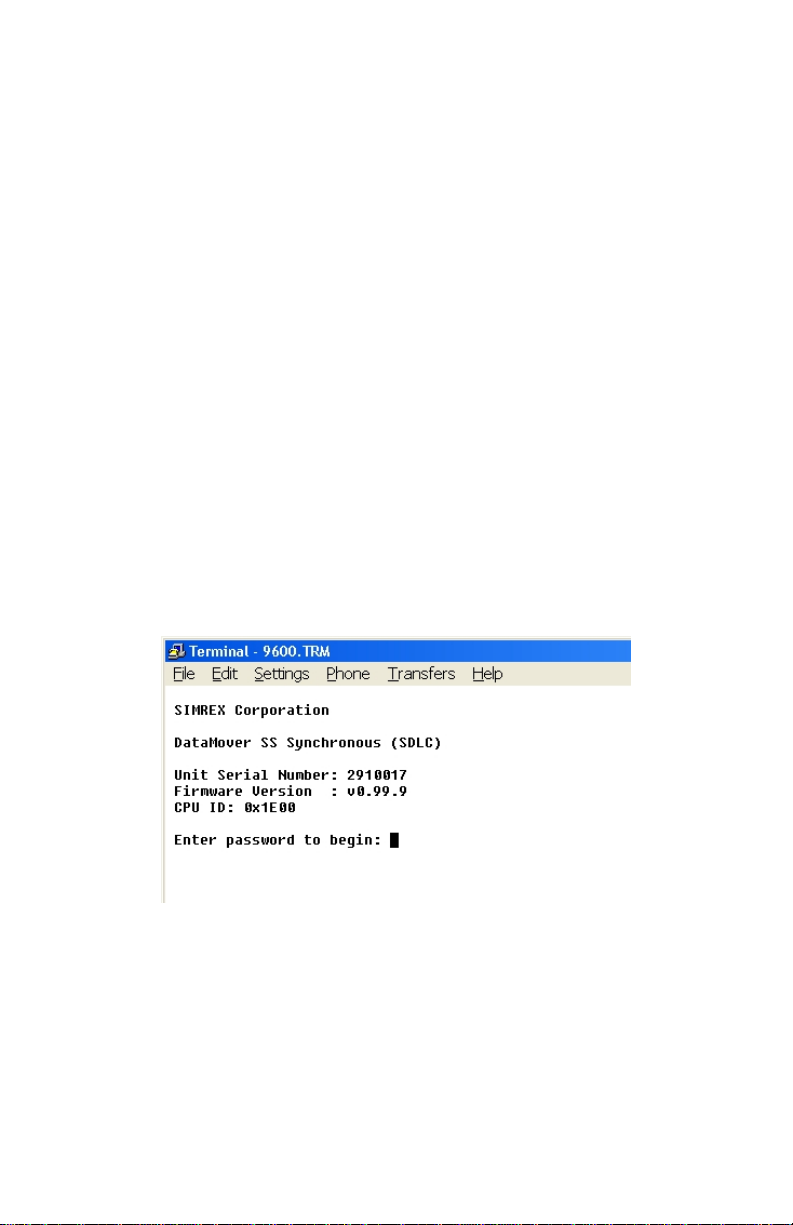
With a terminal program running and the CONFIG port
connected, if the terminal program is set up correctly,
you will see the screen below.
This screen lists the product name, serial number,
firmware revision and it identifies the CPU used inside.
These items are all needed if you need to contact Simrex
for support for any reason.
DataMover SS 900 Synchronous
rev 1.0
SIMREX Corporation
4 of 13
This information is only shown as a sign-on message
when the unit is powered up.
The default password is four nine’s….. 9999
Enter the password and press enter.
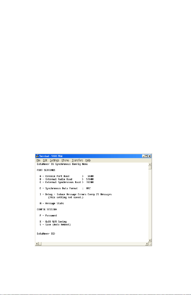
There are only a few settings in the DM SS Sync.
Note, there is no option for whether the DM-SS Synch
outputs the synchronous TX & RX clock. The DM SS
Synch can only output the clock signal. It does not
accept a clock from the connected device.
(Note: In the main menu, items with a > following it
indicate there is a sub-menu if that letter is selected.
Items that have a :following it indicate that the setting
is changed by selecting the letter and pressing return.)

DataMover SS 900 Synchronous
rev 1.0
SIMREX Corporation
5 of 13
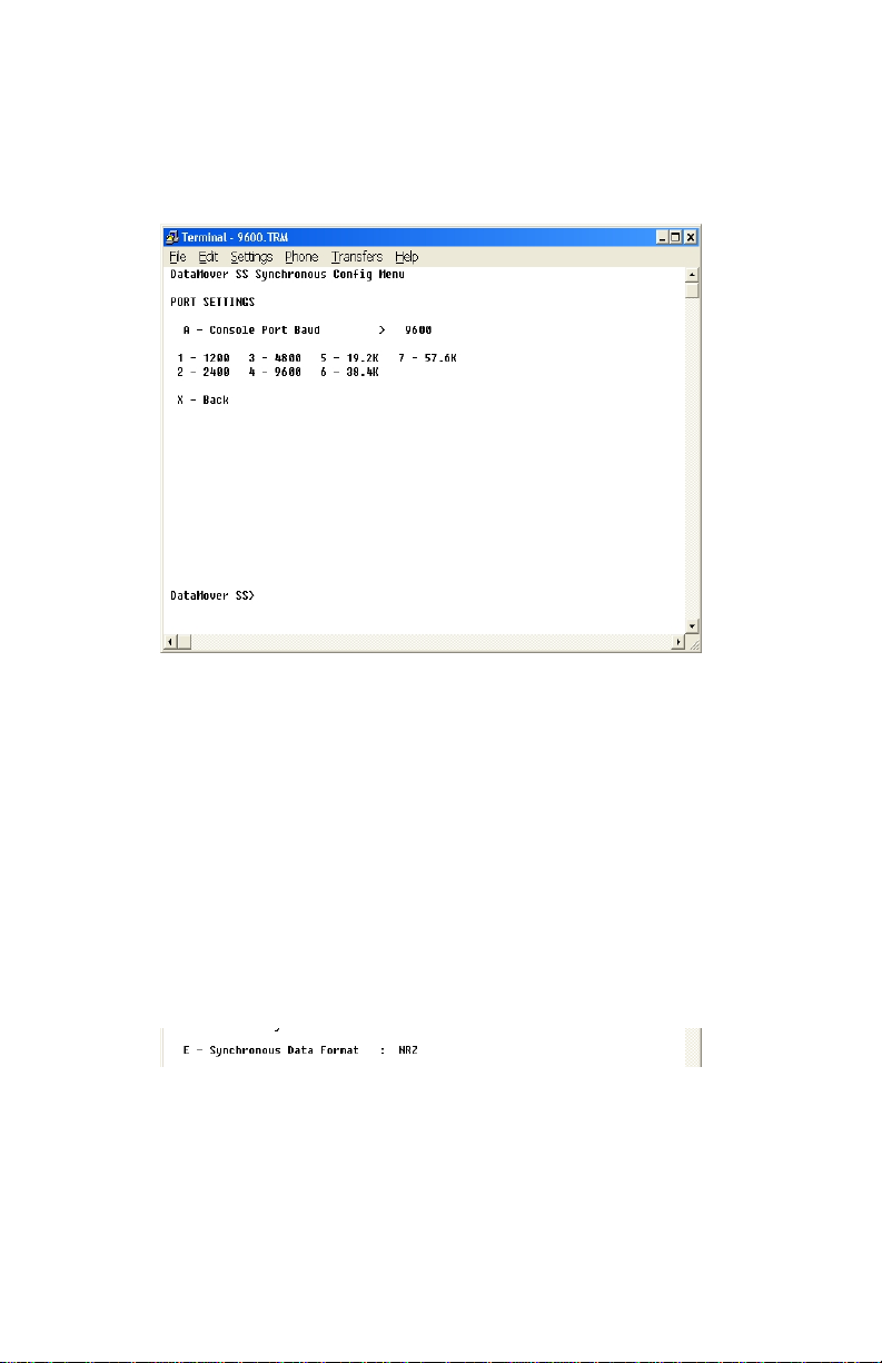
BAUD RATES
Valid baud rates are 1200, 2400, 4800, 19200, 38400,
and 57600.
A - Baud rate for the configuration port
(Terminal/Console)
B - The internal radio baud rate is the speed at
which the CPU inside communicates to the
radio module inside. This baud rate must be
the same between this setting and the
BAUD setting of the radio module itself.
C - This is the baud rate for the connected
synchronous device.
To change any of these settings, select the
corresponding menu letter and press enter. You will be
presented with the following baud rate menu.
DataMover SS 900 Synchronous
rev 1.0
SIMREX Corporation
6 of 13
Press the letter for the desired speed, then press enter.
If the correct selection has been made, enter Xand
press return to get back to the main menu.
The same menu is shown for all three different baud
settings.
DATA FORMAT
The only valid selections are NRZ and NRZI. Most
devices
are NRZ.
To switch between NRZ and NRZI, press E, then press
enter. This toggles the setting.

DataMover SS 900 Synchronous
rev 1.0
SIMREX Corporation
7 of 13
DEBUG SETTING
This feature is only used for debugging purposes.
This setting is NEVER saved, but, if it is used, you must
remember to turn it off, either by explicitly turning it off,
or by power cycling the radio.
What this function does is introduce errors in the data
every 25 messages sent. These errors are over the radio
link only. It will alternate between sending a message
that is one byte short, and then one byte long. These
‘bad’ messages are not passed through to the connected
device, as the over-the-air protocol includes CRC and
length checking.
This function is mainly used for debugging the radio link
itself.
DataMover SS 900 Synchronous
rev 1.0
SIMREX Corporation
8 of 13
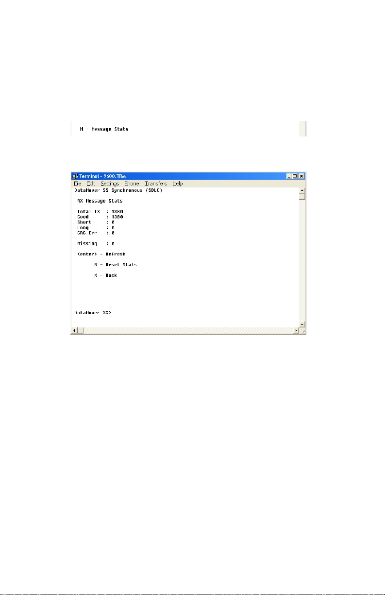
MESSAGE STATS
This selection will display the message stat screen.
Again, the assumption is made that a received message
will be retransmitted on the other transport method, so
these stats only refer to RECEIVED messages over the
RADIO link. If you have enabled ‘Induce Errors’, these
errors will be seen here, but only on the unit that is
receiving from the one with errors enabled.
While in this screen, press enter to refresh the stats.
Press R, then enter to reset all values to zero.
Press X, then enter to return to the main menu.
Table des matières


