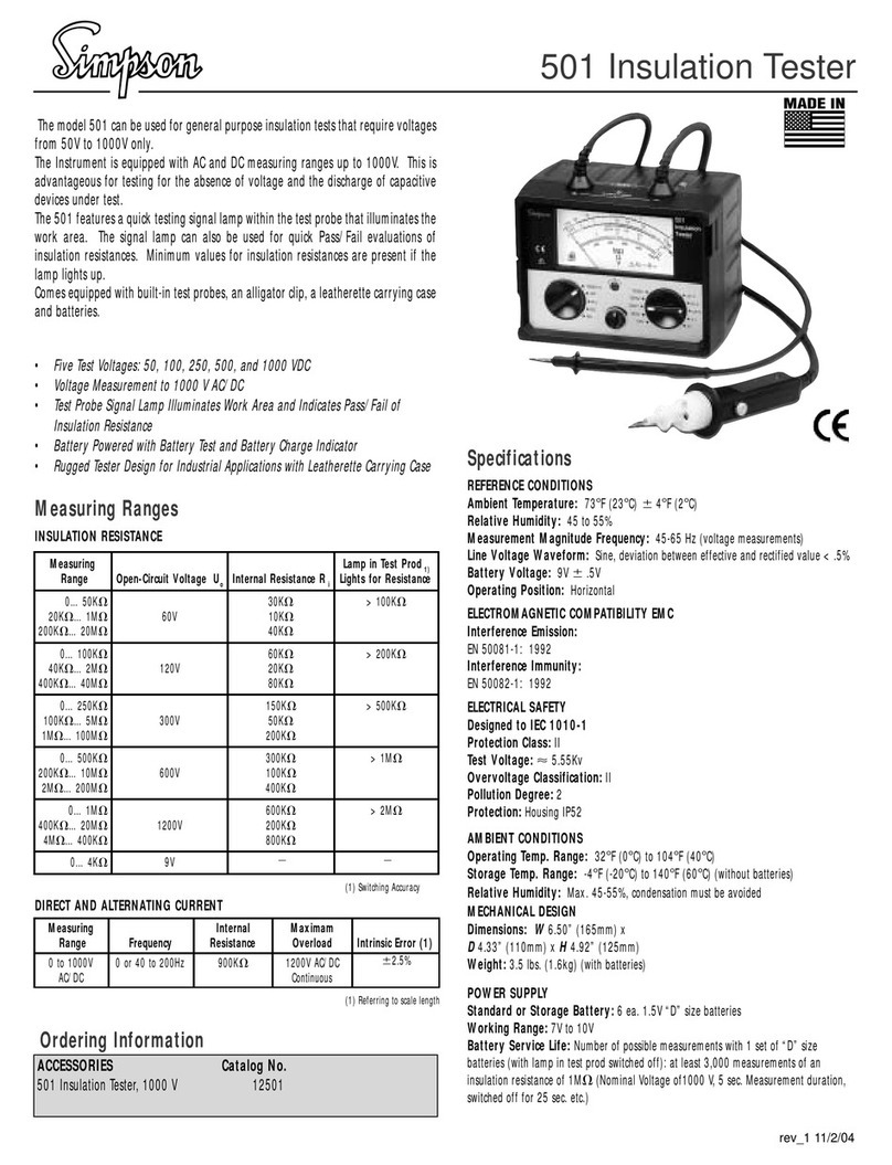
Simpson 505 Manuel utilisateur

505
High Voltage Insulation Tester
INSTRUCTION MANUAL
www. .com information@itm.com1.800.561.8187

2
About this Manual
To the best of our knowledge and at the time written, the information contained in
this document is technically correct and the procedures accurate and adequate
to operate this instrument in compliance with its original advertised specifica-
tions.
Notes and Safety Information
This Operator’s Manual contains warning headings which alert the user to check
for hazardous conditions. These appear throughout this manual where appli-
cable and are defined below. To ensure the safety of operating performance of
this instrument, these instructions must be adhered to.
Warning, refer to accompanying documents.
Caution, risk of electric shock.
2000 V CAT II Overvoltage category II device
Indicates EU conformity
Warranty and Returns
SIMPSON ELECTRIC COMPANY warrants each instrument and other articles
manufactured by it to be free from defects in material and workmanship under
normal use and service, its obligation under this warranty being limited to making
good at its factory or other article of equipment which shall within one (1) year
after delivery of such instrument or other article of equipment to the original pur-
chaser be returned intact to it, or to one of its authorized service centers, with
transportation charges prepaid, and which its examination shall disclose to its
satisfaction to have been thus defective; this warranty being expressly in lieu of all
other warranties expressed or implied and of all other obligations or liabilities on
its part, and SIMPSON ELECTRIC COMPANY neither assumes nor authorizes
any other persons to assume for it any other liability in connection with the sales
of its products.
This warranty shall not apply to any instrument or other article of equipment which
shall have been repaired or altered outside the SIMPSON ELECTRIC COMPANY
factory or authorized service centers, nor which has been subject to misuse,
negligence or accident, incorrect wiring by others, or installation or use not in
accord with instructions furnished by the manufacturer.
!
www. .com information@itm.com1.800.561.8187

3
This manual represents your meter as manufactured at the time of publication. It
assumes standard software. Special versions of software may be fitted, in which
case you will be provided with additional details.
The apparatus has been designed and tested in accordance with EN 61010-1,
“Safety Requirments for Electrical Equipment for Measurement, Control and Labo-
ratory Use.” This operationg guide contains information and warnings that must
be followed by the user to ensure safe operation and to maintain the apparatus in
a safe condition.
We reserve the right to make changes and improvements to the product without
obligation to incorporate these changes and improvements into units previously
shipped.
www. .com information@itm.com1.800.561.8187

4
Contents
1. CONTROLS AND INDICATORS ......................................................... 5
2. SAFETY PRECAUTIONS .................................................................. 5
2.1 Repair and Parts Replacement .............................................................5
2.2 Errors and Extraordinary Strains ........................................................... 6
2.3 Safety Symbols ........................................................................................ 6
3 APPLICATIONS................................................................................. 6
4. INITIAL START-UP ............................................................................ 7
4.1 Battery Installation .................................................................................. 7
4.2 Testing the Batteries ...............................................................................7
4.3 Switching the Tester On and Off .............................................................7
4.4 Analog Display ....................................................................................... 8
5. DIRECT AND ALTERNATING VOLTAGE MEASUREMENTS ............. 8
6. INSULATION RESISTANCE MEASUREMENT .................................. 9
6.1 Measurement Procedure .....................................................................10
6.2 Measurements with the Guard Cable
7 Characteristic Values ....................................................................... 11
7.1 Specifications .......................................................................................12
8 MAINTENANCE .............................................................................. 13
8.1 Batteries ...............................................................................................13
8.2 Housing ................................................................................................13
8.3 Measurement Cables ...........................................................................13
8.4 Repair...................................................................................................14
9 FACTORY SERVICE ........................................................................ 14
10 TECHNICAL ASSISTANCE ............................................................. 14
11 NIST CERTIFICATION .................................................................... 14
6.05 Discharging the Device Under Test .................................................. 9
................................................11
www. .com information@itm.com1.800.561.8187

5
1. CONTROLS AND INDICATORS
1. Range Selector Switch for test voltage, battery test and power supply inter-
ruption
2. Range Key for measuring range selection
3. indicator LED -green: valid measurement
-off: invalid measurement, battery too weak
4. Upper Range LED: indicates 1 T scale is selected
5. Lower Range LED: indicates 100 M scale is selected
6. Adjustor Screw for mechanical zero adjustment
7. Function Selector Switch for voltage or insulation resistance measurements
8. Analog Display
9. Test Probe Negative (-) Measurement Cable
10. Test Probe Positive (+) Measurement Cable
11. Guard Cable Connector Jack
12. Battery Module
2. SAFETY PRECAUTIONS
Simpson’s 505 Insulation Tester is manufactured and tested in accordance with
the following standards:
IEC 1010-1/EN 61010-1,
IEC 61557/EN 61557
In order to maintain flawless technical safety conditions and to assure safe use,
read the operating instructions carefully before using your instrument.
2.1 Repair and Parts Replacement
Voltage conducting parts may be exposed when the instrument is opened. The
instrument must be disconnected from all sources of voltage before repair or
replacement of parts. If the repair of an open, live instrument is unavoidable
instrument must be repaired by trained personnel who are familiar with the risks
involved.
SIMPSON ELECTRIC CO.
Lac Du Flambeau, WI 54538
www. .com information@itm.com1.800.561.8187

6
2.2 Errors and Extraordinary Strains
If suspected that the instrument is no longer operating safely, do not use. Send
the instrument in for repair; see paragraph 8.4.
Instrument will not operate safely if:
• measurement cables are damaged,
• the instrument demonstrates visible damage,
• the pointer no longer responds,
• one of the LEDs is defective,
• the instrument no longer functions,
• after lengthy periods of storage under unfavorable conditions.
Observe the following safety precautions:
• Operate Instrument with batteries or storage batteries. Do not use AC Line
connected power supplies as they are life endangering.
• Watch carefully for unexpected voltages at devices under test. (For example,
capacitors can be dangerously charged.)
• Make certain that measurement cables are in flawless condition, e.g. no dam-
age to insulation, no creases, no interruptions etc.
High Voltage!
Do not touch the test probes or the device under test, (DUT), during voltage testing!
High-voltage of up to 5 kV can be present!
Accumulation of Moisture
Avoid any accumulation of moisture on the tester, on the measurement cables or
on the unit, because leakage currents may be caused by high-voltages at ex-
posed surfaces. Even isolated components may carry high-voltages.
NOTE: Overvoltage Influence
If the reversible fuse (PTC thermistor) responds to an overvoltage or an extrane-
ous voltage, do not resume measurement until a cool-down period of approxi-
mately 2 minutes is observed.
2.3 Safety Symbols
Safety symbols are shown and explained on inside front cover of this manual.
3. APPLICATIONS
The MODEL 505 Insulation Tester complies with regulation IEC 61557/EN 61557
“Measuring and Monitoring Equipment for the Testing of Electrical Safety in Sys-
tems with Nominal Voltages of up to AC 1000 V and DC 1500 V”.
Part 2, insulation resistance testers.
It is suited to measure insulation resistance for devices and systems in a voltage-
free condition with nominal voltages of up to 1000 V. It is also suited for measuring
insulation resistance of up to 1 T with open-circuit voltages of up to 5000 V.
!
www. .com information@itm.com1.800.561.8187

7
The tester is also equipped with a 2000 V measuring range for direct and alter-
nating voltages. This is especially advantageous for testing for the absence of
voltage, and for discharging of capacitive units under test.
4. INITIAL START-UP
4.1 Battery Installation
Before opening the battery compartment (side panel) be sure that the Function
Selector switch is set to the “V” position, and that the Range Selector switch is set
to the “OFF/V” position, and that the device is completely disconnected from all
external power circuits.
1. Unscrew and remove battery compartment.
2. Remove battery clip.
3. Pull battery holder out of battery compartment.
4. Insert six commercially available 1.5 V, 6.0 AH, “D” size batteries or storage
batteries (single cell) into battery holder with polarity as indicated by
symbols.
5. Push battery holder back into battery compartment.
6. Push battery clip back over contacts making certain that correct polarity
is assured.
7. Reinstall battery compartment to the housing in the correct direction (label-
ing must be legible) and fasten with screws.
4.2 Testing the Batteries
NOTE: If pointer only moves into minimal supply voltage range, several mea-
surements can still be performed for test voltages of less than 1000 V, because
the battery test is conducted with the same load as is used for a test voltage of
1000V.
4.3 Switching the Tester On and Off
As long as the Function Selector switch is set to and the Range Selector switch
is not in the OFF/ V position, tester remains activated. For transportation and
maintenance purposes, it is recommended that the Function Selector switch be
set to the V position, and the Range Selector switch be set to the OFF/ V position
in order to prevent unintentional activation.
NOTE: Be certain that the grip on the Function Selector switch points exactly to
“V” or “ ”. This is especially important during discharging of capacitive devices
under test, because voltages are not displayed in intermediate selector switch
positions.
!
After batteries have been installed, or if indicator LED fails to light during
insulation resistance measurement, test batteries. For battery testing, the
Range Selector switch must briefly be set to the position. Deflection of pointer
on the analog dial within the scale during battery test indicates the condition of
batteries or storage batteries at an average load of 1000 V test voltage. The
position of the Function Selector switch will not affect battery test results. The left
end of the scale represents minimum required supply voltage, and the right end
represents maximum available supply voltage.
www. .com information@itm.com1.800.561.8187

8
4.4 Analog Display
Logarithmic representation of the upper resistance scale allows for quick recog-
nition of the magnitude involved. In order to achieve the required accuracy for
testing of protective measures, the RANGE key allows for switching to the ex-
panded lower limit measuring range of 100 k ... 100 M . The orange colored
Upper Range and Lower Range LEDs, at the right end of the scale indicate
which of the two resistance measuring ranges is currently active.
The indicator LED lights green to confirm correct insulation measurement. If
LED does not light, test voltage has not been achieved. If this happens test the
battery. The two lower scales are for battery testing and voltage measurement,
see paragraph 4.2 and 5 respectively.
5. DIRECT AND ALTERNATING VOLTAGE
MEASUREMENTS
Direct voltages and sinusoidal alternating voltages with frequencies ranging
from 15 to 500 Hz can be measured with the tester. Deflection of the pointer of the
instrument is always positive for direct voltage measurements, regardless of
polarity at the connections. Alternating voltage is indicated as an effective value.
Voltage measurements are used to test for the absence of voltage before insula-
tion resistance measurements, as well as for the automatic discharge of capaci-
tive devices under test. The voltage drop can be observed at the display.
NOTE: Regardless of the position of the Range Selector switch, voltage mea-
surement can always be performed with Function Selector switch in the “V” posi-
tion (even without batteries).
1. Set Function Selector switch to “V” position.
2. Check that pointer is at “0” in the V scale when the test probes are not
connected. Reset the pointer as required using Adjustor screw for mechani-
cal zero adjustment.
3. Position of Range selector switch has no influence on voltage measure-
ments, although we recommend setting it to the OFF/ V position.
4. Contact measuring points with both test probes.
5. Read measurement value at V scale.
NOTE: Voltages greater than 2000 V may not be applied. Input resistance for
voltage measuring range is equal to 5 M .
www. .com information@itm.com1.800.561.8187

6. INSULATION RESISTANCE MEASUREMENT
Be certain that the device under test (DUT) is voltage-free before preforming
measurements; see paragraph 5. If voltage is present see paragraph 6.05.
For measurements over 10 G 1, the guard cable (cat. No 45065) is
recommended; see paragraph 6.3.
6.05 DISCHARGING THE DEVICE UNDER TEST
The function selector switch must be switched from 1back to V, in order to
discharge test voltage from DUT. The range selector switch can be left at the
original setting.
9
www. .com information@itm.com1.800.561.8187

10
6.1 Measurement Procedure
1. Set Function Selector switch to position, in order to activate test voltage.
2. A range of either 10 k ...1 T or 100 k ... 100 M can be pre-selected with
the RANGE key.
3. Select the required nominal voltage of 100 V, 250 V, 500 V, 1000 V, 1500 V,
2000 V, 2500 V, or 5000 V with the Range Selector switch depending upon
the nominal voltage of the D U T . The Upper and Lower Range LED’s
indicated the selected range, 10k ...1 T or 100k ... 100M . To begin,
select the 10 k ... 1 T range with the RANGE key. Upper Range LED will
light.
4. Contact the measuring point with both test probes and wait until pointer has
settled. Depending on the DUT, this might take up to 30 seconds, if, for
example, large capacities (long cables) must be charged.
5. Read the measurement value from the upper scale. If the green LED
indicator lights, the insulation measurement is valid. If this LED does not
light, test voltage has not been achieved. If this happens, test the battery; see
paragraph 4.2.
6. In order to achieve the required accuracy for testing of protective measures,
select the high resolution range, 100 k ... 100 M with the help of the RANGE
key. The Lower Range LED lights.
7. Contact the measuring point with both test probes once again.
8. Read the measurement value from the lower scale.
Do not touch conductive ends of test probes when tester has been activated for
measurement of insulation resistance.
This may cause an electric shock, which, although not life endagering, causes a
clearly distinguishable shock.
When measurements are made at capacitive devices under test, e.g. cables, the
DUT may be charged with voltages of up to approximately 5000 V, depending
upon selected nominal voltage. Contact with the DUT test after measurement
is, in this event, life endangering!
For this reason the DUT must be discharged in a controlled fashion by switching
Function Selector switch to V and contacting the DUT with the test probes until
measurement display indicates 0 V. Do not reverse the polarity of DUT during
discharging, because internal over-voltage protection would otherwise be
triggered. If the capacitance to be discharged is greater than 3mF,
polarity must not be reversed, because unit might otherwise be damaged.
NOTE: Overvoltage Influence
If the reversible fuse (PTC thermistor) responds to an overvoltage or an extrane-
ous voltage, do not resume measurement until a cool-down period of approxi-
mately 2 minutes is observed.
!
www. .com information@itm.com1.800.561.8187
Table des matières
Autres manuels Simpson Équipement de test

Simpson
Simpson 385-3L Manuel utilisateur

Simpson
Simpson 42115 Manuel utilisateur

Simpson
Simpson 42145 Manuel utilisateur

Simpson
Simpson 887-2 Manuel utilisateur

Simpson
Simpson 890-2 Manuel utilisateur

Simpson
Simpson 501 Manuel utilisateur

Simpson
Simpson 228 Manuel utilisateur

Simpson
Simpson 229-2 Manuel utilisateur
Manuels Équipement de test populaires d'autres marques

SMART
SMART KANAAD SBT XTREME 3G Series Manuel utilisateur

Agilent Technologies
Agilent Technologies BERT Serial Manuel utilisateur

Agilent Technologies
Agilent Technologies N3280A Manuel utilisateur

Vernier
Vernier Go Direct Voltage Manuel utilisateur

Lifeloc
Lifeloc R.A.D.A.R. Manuel utilisateur

Fluke
Fluke T5-600 Instructions d'utilisation et d'installation