Eject®Helmet Removal System
Installation, User Instructions and Safety Information
Figure A-1.
Figure A.
Bladder Connector
Eject®Bulb Inator
Eject®Bladder
Eject®Equipped
Helmet Sticker
Eject®Expiration Date
Sticker
Eject®Practice Bladder
Date Helmet Kit Installed:
Replace in 24 months
Figure B.
Le side of rider/
driver’s helmet
Right side of rider/
driver’s helmet
e E j e c t ®Helmet Removal System does not
and cannot eliminate motorsports injuries
such as severe brain, head and neck injuries.
NOTICE
INSTALLATION NOTES: If you have
purchased a practice bladder – install the
practice bladder rst, and then follow the
practice bladder instructions on the second
side of these instructions before installing the
permanent bladder. e practice bladder may
be reused – the permanent bladder may not.
Prior to installing the helmet unit, li the clear
ap at the bottom of the expiration date sticker,
record the date of helmet installation, remove
the backing material from the sticker, and press
the clear protective layer onto the bottom half
of the label.
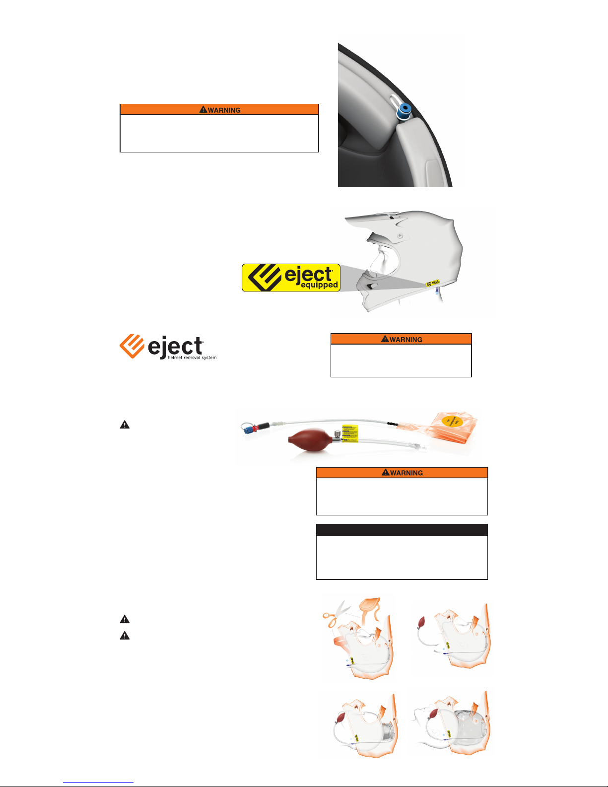
1. Place the helmet upside down with the chin
bar facing away from you. (Figure A.)
2. Study liner design and available removable
liner pieces to gain access to the hard foam
under the so lining foam. Evaluate the
openings/gaps in the so foam for the exit
path of the tube to the rider/driver’s le side of
the helmet. Place the Eject®Bladder under the
so helmet liner as shown in Figure A-1.
A small cut may be required in the so lining
of some helmets to feed the tube through.
DO NOT CUT INTO THE HARD FOAM
LINER.
3. Position the Eject®Bladder centrally inside the
top of the helmet with the plastic tube exiting
to the rider/driver’s le. Do not permanently
attach the Eject®Bladder at this stage. When
the helmet is on, the Eject®sticker and tube
tting must be on the rider/driver’s le side.
4. Feed the ination tube behind
the helmet lining until the tube
rests along the inside of the
helmet, allowing the bladder to
be positioned in the center as shown in
Figure B.
e E j e c t ®Bladder must not be restricted
from ination/expansion. e helmet liner or
crown pad must not be glued or attached in a
way that will hinder the ination/expansion
of the Eject®Bladder.
Package may contain any of the following:
Installation Instructions: Helmet Kit
Installation instructions continued on reverse side.
• You must completely understand all Eject®Helmet
Removal System User Instructions and safety information
before using and installing this product.
• Simpson recommends that the Eject®system only be
inated by professional rescue personnel trained in the
use of the Eject®system.
• If you have purchased the bulb inator be sure to carry
these instructions with the
bulb inator.
• You should discuss the use of Eject®with
the owner or manager of the track where
you ride/drive. Leave a copy of this helmet removal
instruction manual with the track owner, manager, or
family member or friend at the track who can provide them
to a trained rst responder if there is no one on site who is
trained in the use of Eject®.
• To ensure optimal performance,
Simpson recommends replacing
the Eject®system every 24 months.
• Once Eject®is inated, it should be
removed and disposed of.
• Contact the Eject®Support Center at 1-800-654-7223 or
training materials or technical questions.
• Visit SimpsonRaceProducts.com
IMPORTANT SAFETY INFORMATION
READ BEFORE CONTINUING
Alternative routing of the tubing may
be required on some helmets. Ensure
that tube connector exits the le side
of the helmet.
Check that the tubing is not pinched
or kinked at any point along its’
length.
Go to SimpsonRaceProducts.com to
view a video version of the installation
instructions.
DO NOT modify the helmet in any way.