Assembly instructions for kit #15
All rights reserved. 2005 Simple Motors, LLC ♦www.simplemotor.com ♦ 4
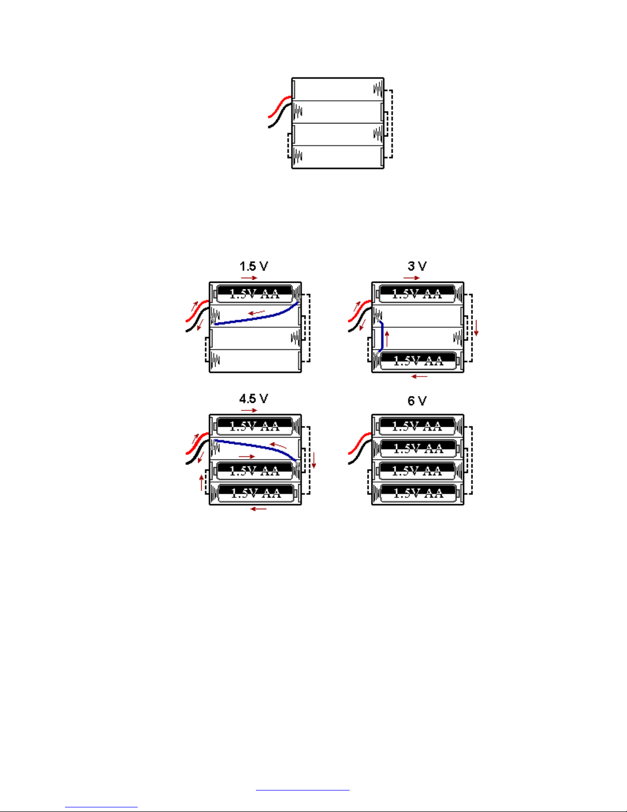
6. The battery holder and a jumper wire included in this kit allow you to experiment with 4
different voltages: 1.5, 3, 4.5, and 6 Volts. To understand how the jumper wire works let's
take a look at the connections inside a typical battery holder:
The following diagram shows how to get 1.5, 3, 4.5, and 6 Volts using 1, 2, 3, or 4 batteries
and a jumper wire shown in blue color. Arrows show the current flow for 1.5, 3, and 4.5
Volts settings. Could you trace the current when all 4 batteries are inserted (there is no
jumper wire in this case)?
Inspect your battery holder – it may have different connections inside. In this case you can
still use the jumper wire in the same manner to get all 4 voltages, but you will need to find
appropriate connection points for each voltage setting.
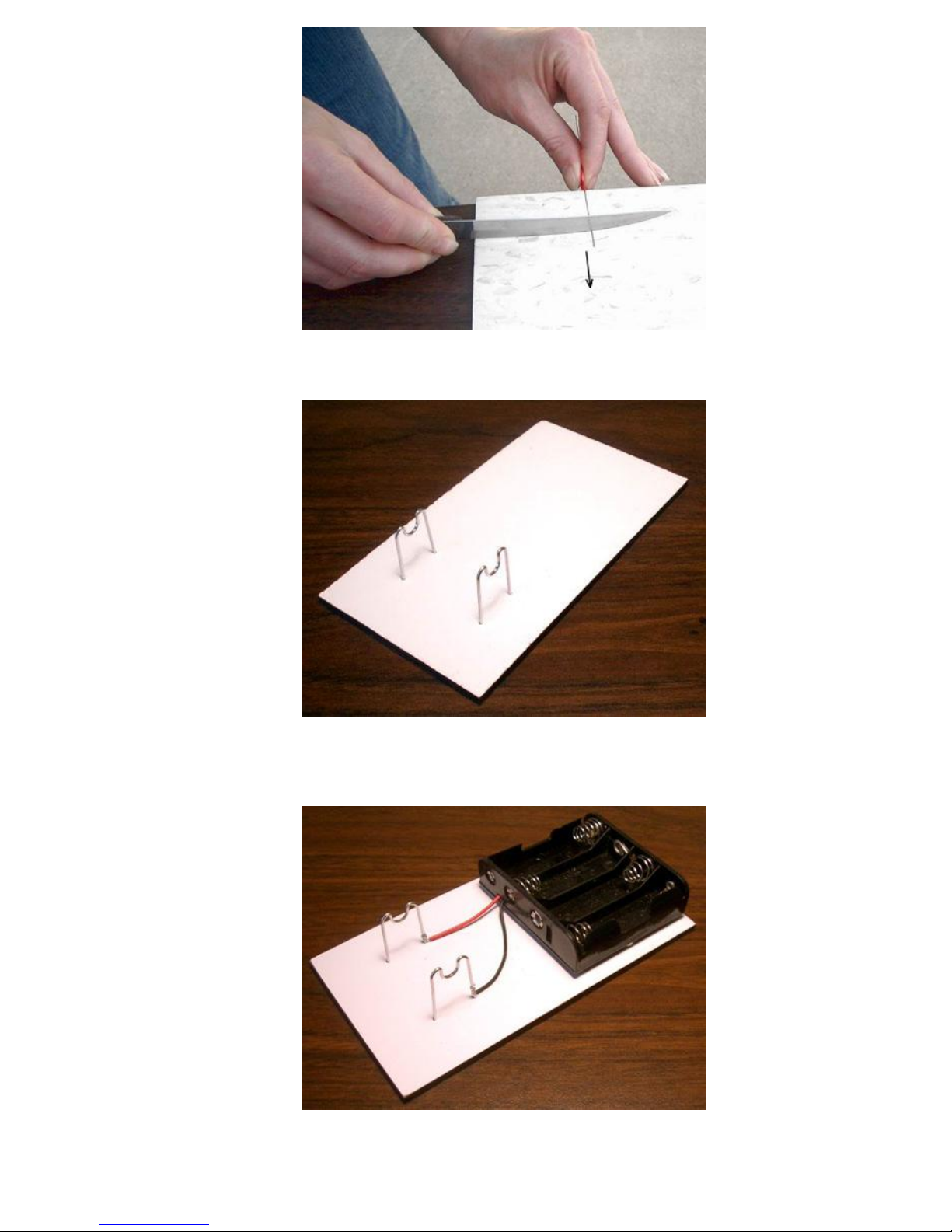
Insert bare ends of the jumper wire between the spring and plastic case to make a good
contact and hold them in place.
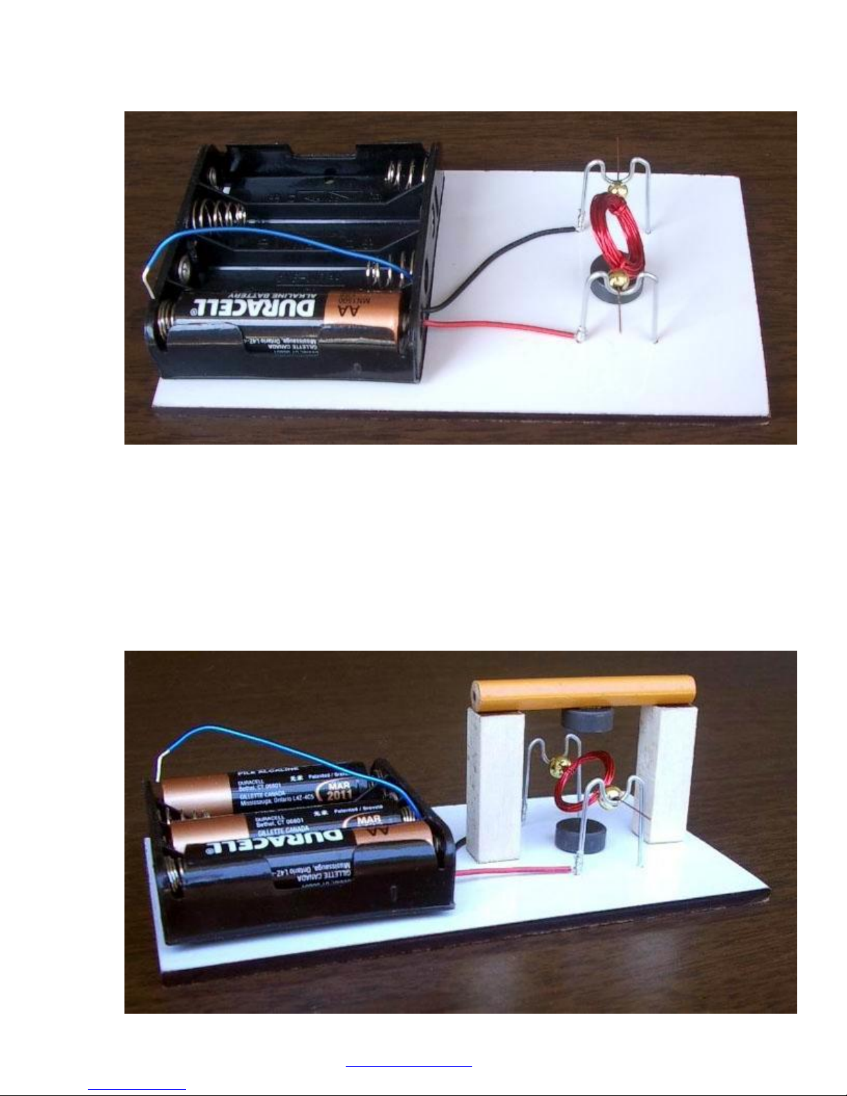
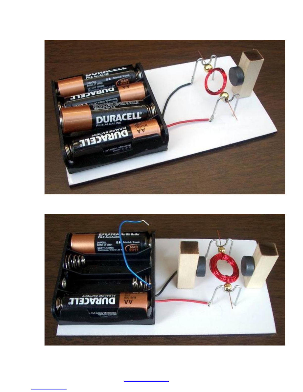
7. Glue the magnet to the board between the stands as shown on the next page. Place two
beads on the coil ends. These beads reduce the friction between the coil and the stands.
Now place the coil on the stands and try to spin it slightly. Well balanced coil should spin
freely. Ideally it should stop in random positions. Take time to balance it. You might need to
move the ends up and down along the coil slightly to find the most balanced position. After
you balance the coil you may add couple drops of glue where the ends meet the coil to
prevent future sliding.