Sim-Lab XP-1 Manuel utilisateur

XP-1 PEDALS
VERSION 1.0
Last updated: 11-09-2023
INSTRUCTION MANUAL
2|2 16
BEFORE YOU START:
Thank you for your purchase. In this manual we will provide you with the means to
get started using your new pedals!
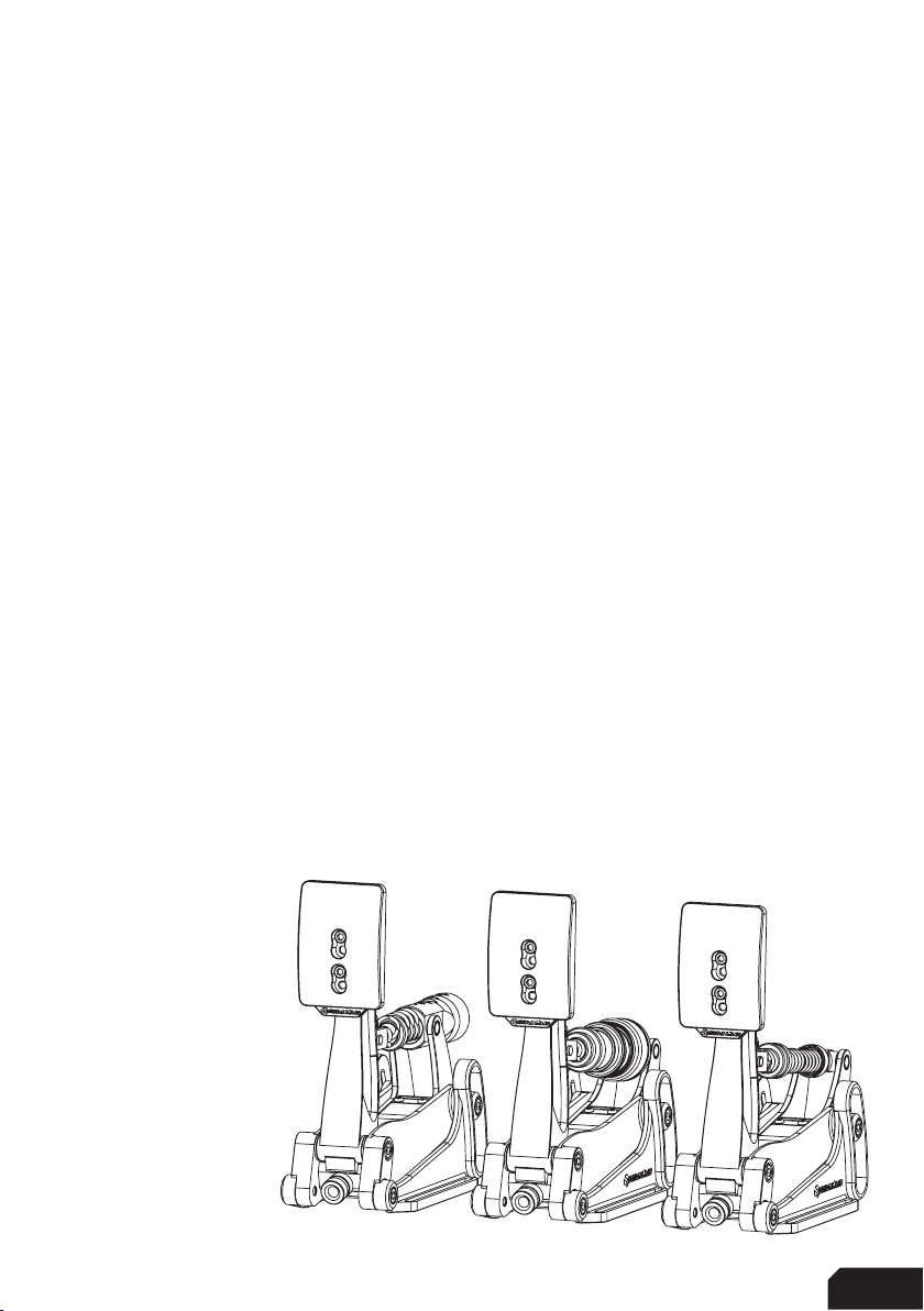
Introducing the Sim-Lab XP-1 200KG Loadcell Pedal Set! Simulate any pedal of any
car with the most complete sim-racing pedal set available. Carefully crafted to satisfy
the needs of serious sim racing enthusiasts, this top-notch and fully customizable
pedal set is designed to take your on-track performance to new heights. Experience
the thrill of absolute control, immerse yourself in the authenticity of sim racing, and
unleash your true racing potential with the Sim-Lab XP-1 200KG Loadcell Pedal Set.
It’s time to elevate your racing experience and leave your competitors in the dust.
XP-1 LC PEDAL SET and CLUTCH
Features:
Aluminum construction
Custom integrated loadcell (Brake)
Hall sensor (Throttle/Clutch)
Multiple elastomers included
Multiple springs included
Plug and play (USB-B)
16-Bit resolution input
3
| |316 16
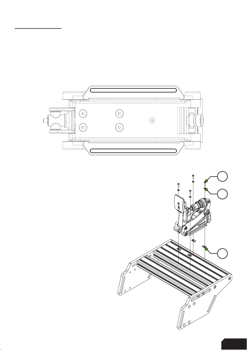
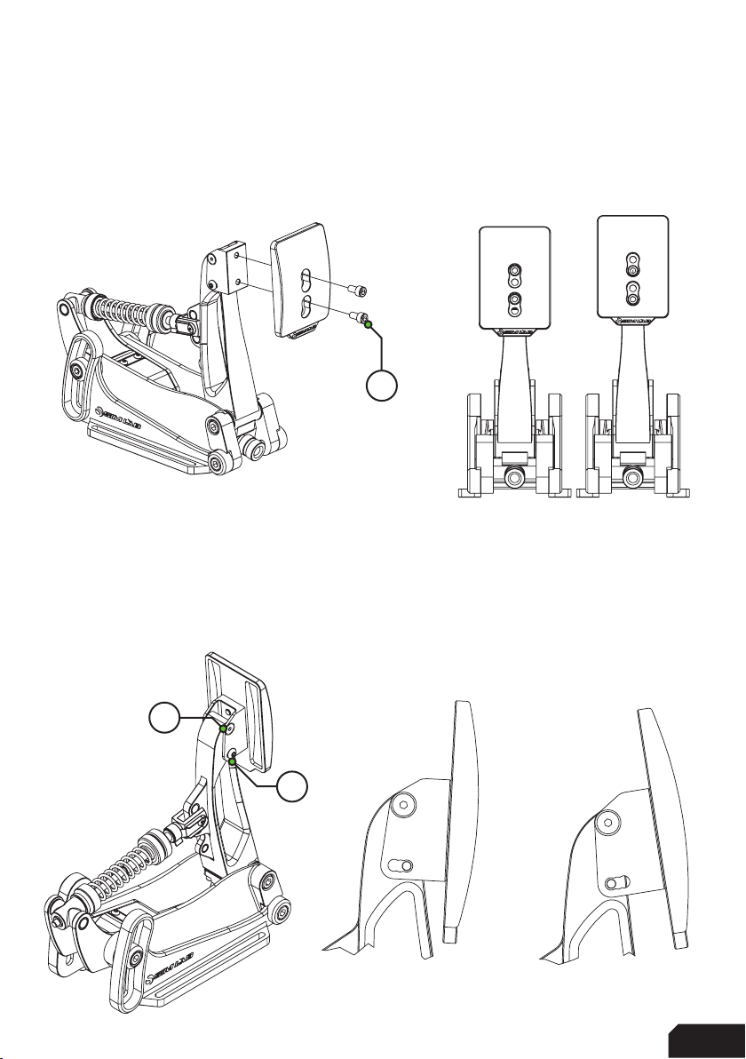
Installation
Depending on your setup, the pedals can be mounted directly to both profile (P1-X) or
pedal decks (like the GT1-EVO). Also the latest universal baseplate is also compatible
with these new pedals so no matter which setup you own, there are ways to mount
this pedal set.
Simply bolt down the set using the 6mm slots (seen from the bottom) shown below.
Profile based pedal deck
In the case of a profile based pedal deck, like found on
the P1-X, mounting is very easy. Sufficient mounting
hardware is included.
The example on the right shows the pedals mounted to
the bigger of the two profiles to allow for a heelplate
to be fitted on the smaller profile. This of course
depends on your preference.
On the next page, you can review our recommended
mounting solutions for pedal decks and baseplates.
A15
A12
A20
4|4 16
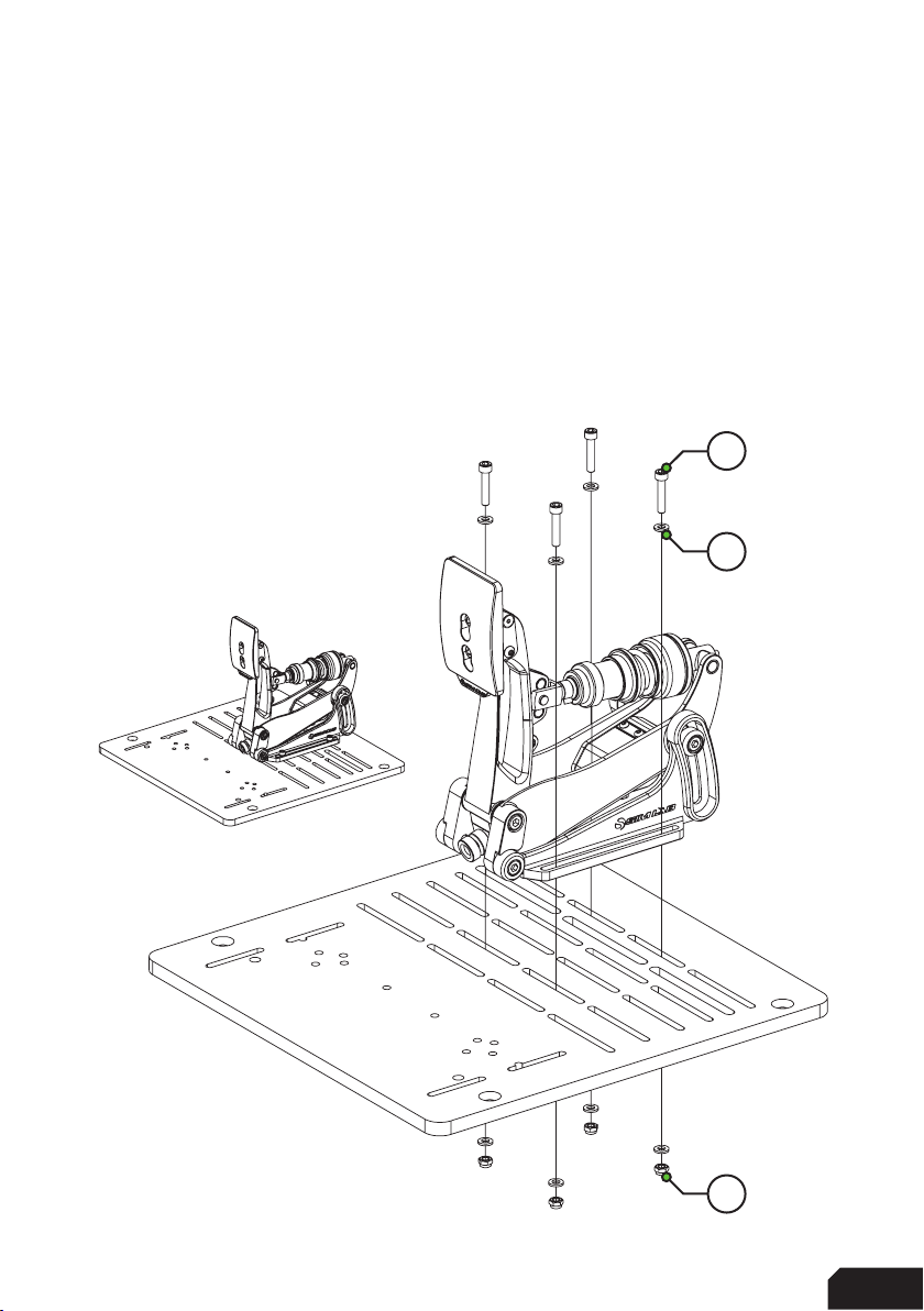
Pedal deck and baseplate
Due to the 6mm slots, you can use almost every slot found on these products and it
all comes down to personal preference.
For baseplates, there still more than enough of possibilities.
The obvious difference here is the lack of slot-nuts, and the inclusion of some
additional washers to help protect your baseplate. As mentioned, the exact slots you
use really don’t matter too much, as almost all slots on our pedal deck based
products match the 6mm slots on the pedal side mounts.
When mounting to a pedal slider
baseplate for example, use the
hardware indicated on the right.
For normal pedal decks, the same
hardware applies. The bolts will
stick out a bit, that is okay.
A18
A15
A11
5
| |516 16
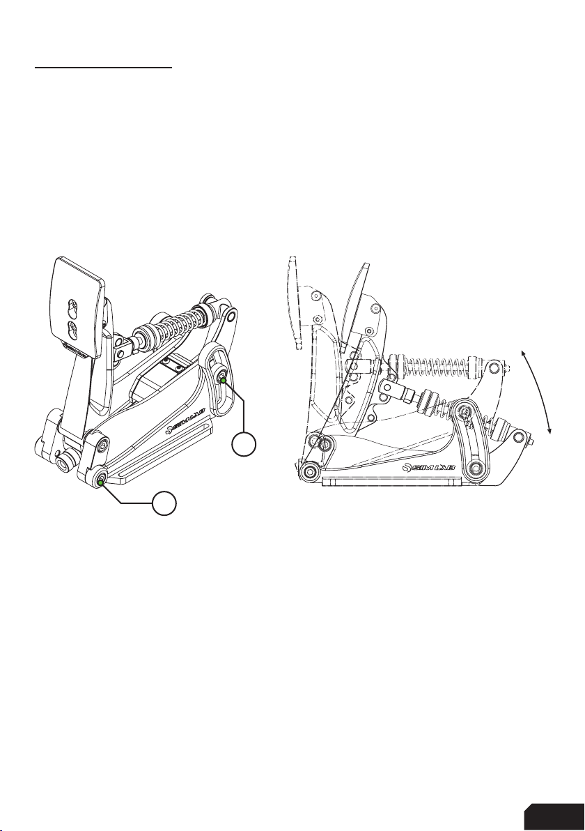
Configuration
Pedal Base
We tried to re-use as many parts throughout the pedals as possible. This means the
configuration and adjustments are virtually the same for all three pedals.
The angle of the pedal arm in relation to your cockpit can be changed by adjusting
the pedal base. Simply loosen four bolts, start with the two (P) where the arm pivots
around. After those are loose, loosen the two (A) in the arcs. Now you should be able
to rotate the entire pedal as a whole while the base remains fixed in place. Tighten all
bolts again after you have found your preferred position and you are good to go.
There is quite a large range of adjustment (20 degrees) possible so you can adjust
these pedals to your seating position perfectly.
Note: especially for the brake pedal, make sure all four bolts (A,P) are tight
before using the pedal with higher brake forces.
A
P
6|6 16
Pedal Face
One of the more simple adjustments is the ability to change the position and angle
of the pedal face. Loosen the two bolts (F) holding the pedal face and you can adjust
the position of the pedal face to your preference.
As mentioned, it is also possible to change the angle of the pedal face. Begin by
loosening the top (T) (countersunk) bolts, but do not remove them. Temporarily
remove the bottom (B) bolts and now the bracket can rotate freely. The bracket
comes with a preset slot for different angles you can choose from. Choose your
angle and fix it in place using the two bottom bolts (B). When happy, tighten the
upper two (T) bolts again as well.
B
T
F
7
| |716 16
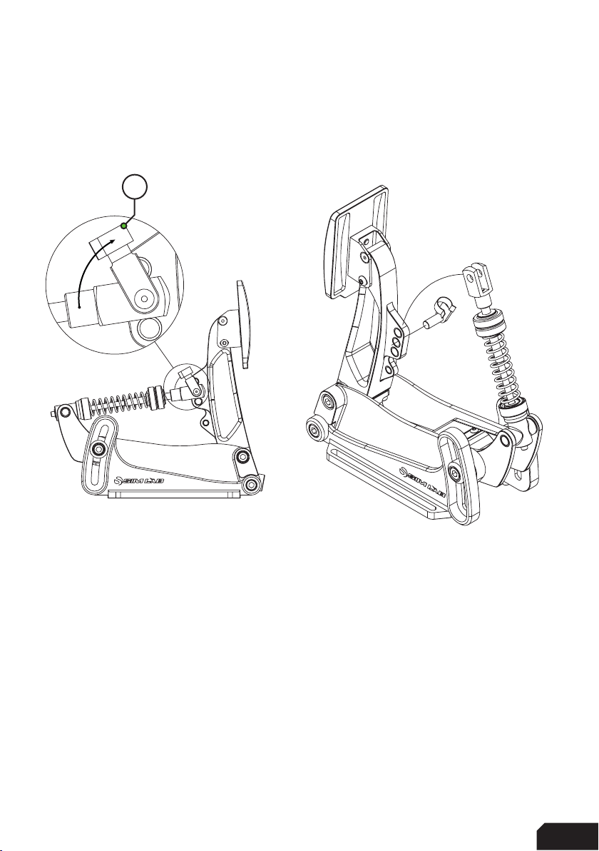
Prepare for changing parts
To get acces to the parts we can change, first we must temporarily remove the
spring bolt (S), which keeps the clevis fork attached to the pedal arm. In this example
we are using the throttle pedal.
Release any tension from the spring by loosening any adjustment knob(s) before
trying to remove the spring bolt.
Unclip the spring bolt (S) from the clevis fork shaft (left drawing) by rotating it up-
wards, then pull it away from the clevis fork altogether. Now the entire shaft holding
parts, can be turned away from the pedal arm and as many parts removed as
desired.
Be careful! The pedal arm is unsupported right now and will be able to fall towards
the front or the rear of the pedal. We recommend to keep holding the pedal arm or
provide support to it by other means, while removing the clevis fork and shaft parts,
to avoid damage.
S
8|8 16
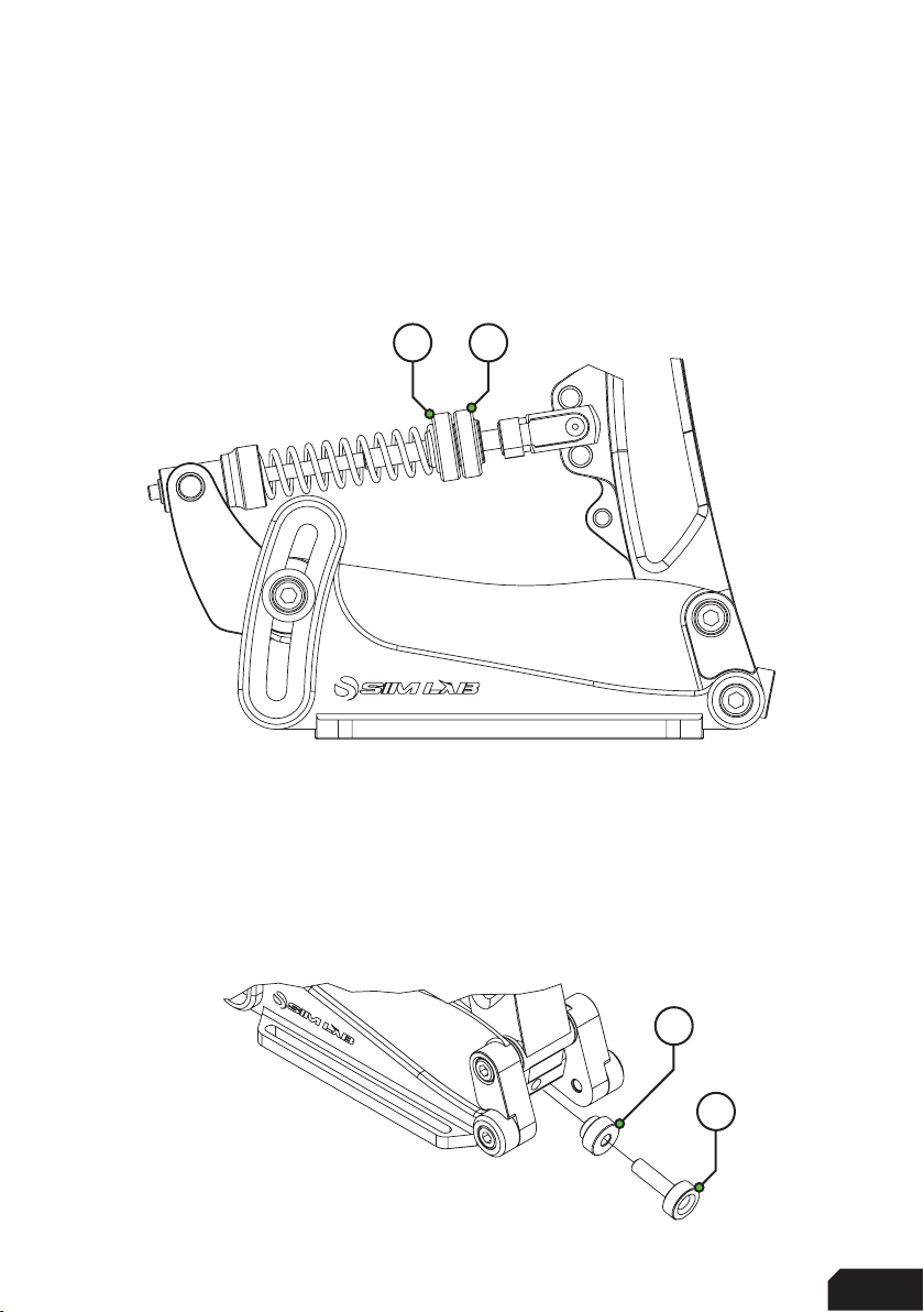
Throttle configuration
This pedal is easy to setup, be it stock or after you have changed the springs. There
are two main options basically. The throttle spring can be adjusted to be more stiff
or soft. Unlock the blue knobs and tighten (clockwise) the adjustment knob (A) for
a stiffer throttle feel. To go softer, do the opposite. When you are happy with the
change, hold the adjustment knob (A) and tighten the locking knob (L) against it, this
locks your change in place.
The same principle applies to the maximum travel of the pedal. On the bottom of the
pedal arm you will find two blue knobs as well. The inner one is the locking knob (L),
the outer one is the adjustment knob (A). Turning the adjustment knob clockwise
results in less travel, turning the adjustment knob anti-clockwise results in more
travel. By default, the pedal has been setup to provide a middle of the road range of
travel but you are free to experiment.
L A
L
A

9
| |916 16
Adjusting spring force isn’t only possible by using the adjustment knobs. Using the
lower of the three adjustment points on the pedal arm gives you a slightly softer (S)
pedal pressure for example. The higher of the three a slightly firmer (F).
Note: by the nature of the position of the clevis fork so low on the pedal arm, travel
might be mechanically limited. Please do check the travel manually (meaning literally,
by hand) to see if you need to decrease travel using the travel adjustment knobs,to
prevent the clevis fork interfering with the flange on the pedal arm. When it does,
please reduce maximum travel until you have about 3-4mm between the flat base
of the clevis fork and the pedal arm flange.
In case you aren’t happy with the overall spring force range, we supply a heavy
throttle spring for ultimate control. Simply follow the steps on page 7, remove the
adjustment knobs and replace the default spring with the heavy one.
F
S
10 |10 16
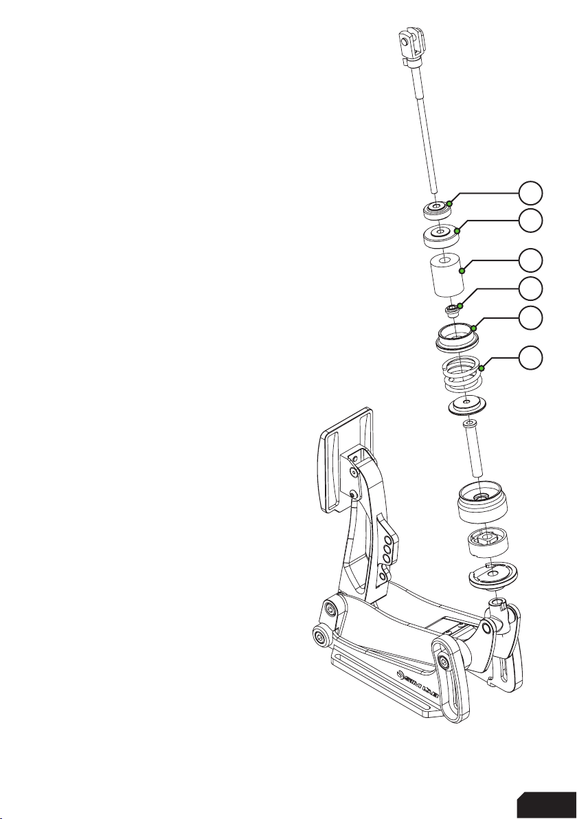
Brake configuration
We will focus just on changing parts in this chapter.
After you have followed the steps on page 7, you
can now remove the clevis fork and shaft. This makes it very
easy to change around parts to suit your preference.
Keep in mind, all parts connected to the shaft are
loose fitting. Make sure to keep parts together
which don’t need to be replaced to avoid
misplacing them.
The parts which we expect to be removed when
changing the brake stack as shown on the right:
Locking Knob (L)
Adjustment Knob (A)
Elastomer (E)
Bushing (B)
Elastomer Washer (W)
Pre-load Spring (P)
Depending on your preference, we have
included four elastomers (E) in different
hardness (Shore A) ratings for you to try.
The medium one is pre-installed.
Included are the following
elastomers, the Shore A ratings are:
Soft - Shore 50A
Medium - Shore 60A
Hard - Shore 70A
We recommend to match your max pressure
to the elastomer rating. We expect you to run lower
pressures with the 50A, this ensures its durability.
We also supply you with different preload springs to
adjust the feel of the preload. The medium strength one is fitted.
L
A
E
W
P
B
Table des matières
Manuels Pédale musicale populaires d'autres marques


Matthews Effects
Matthews Effects Whaler V2 Manuel utilisateur

Grid 1
Grid 1 Pedal Jeanie Manuel utilisateur

Amptweaker
Amptweaker tightboost Manuel utilisateur

Ibanez
Ibanez TS-808 Tube Screamer Overdrive Pro Manuel utilisateur

PuzzleSounds
PuzzleSounds DR. Q ENVELOPE FILTER Manuel utilisateur

BYOC
BYOC Analog Chorus Manuel


