2 of 2
Testing and Wiring Outstation Lines
Outstation lines require 2-core enhanced fire-rated cable, size 1.0 mm2to 1.5 mm2. The maximum recommended
cable resistance is 40 ohms, which is 1 km of 1 mm2cable. If exceeded, outstations may not work correctly, e.g. audio
quality may degrade and the fault monitoring system may not work.
CAUTION: DO NOT test wiring using an insulation resistance tester (Megger) with any electronic equipment
connected. The 500 volt test will destroy the components, which the factory warranty will not cover.
Test all outstation lines for faults BEFORE termination. In addition, test outstation
lines using a SigTEL FITT telephone line tester.
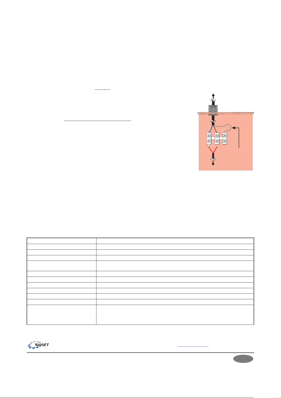
After testing outstation lines, terminate the cable from the EVCS controller at the
outstation’s terminals and reconnect the handset’s wires at the same terminals (see
right).
Secure the outstation’s internal phone housing back in position by pressing firmly on
the phone housing whilst avoiding trapping any wires. Reinsert the two fixing screws.
Refer to the main installation manual for connections at the EVCS controller.
Commissioning the Outstation
Perform an automatic configuration at the master EVCS controller to enable the
system to search for connected outstations. Refer to the main installation manual
for commissioning procedures.
OPERATION
Making a Call from the Outstation
Open the outstation’s door and lift the handset off-hook. The outstation will automatically call the operator in the
control room and a ‘beep-beep’ ringing tone sounds in the outstation’s earpiece. In the control room, the operator
is notified of the incoming call and can choose to answer. An engaged tone (continuous short pips) sounds in the
earpiece if the operator is talking to another outstation. When the call is answered in the control room the ringing
tone stops and a two-way conversation can commence. To end the call, simply replace the handset back on-hook.
Receiving a Call at the Outstation
When the operator in the control room calls the outstation, a pulsed ringing tone is heard at the outstation and the
red LEDs flash. Open the outstation’s door and lift the handset. The ringing tone stops and a two-way conversation
can commence.
TECHNICAL SPECIFICATION EVC302RPO/EVC302RLK
E&OE. No responsibility can be accepted by the manufacturer or distributors of this product for any misinterpretation of this instruction or the
compliance of the system as a whole. The manufacturer’s policy is one of continuous improvement and we reserve the right to make changes to
product specifications at our discretion and without prior notice.
SigTEL
Emergency Voice
Communication System
To EVCS controller
BrownBlue
Red
To handset
Outstation’s phone
housing removed
Red Screened cable is
shown terminated
but is not used
Input voltage (from EVCS controller): 10.7 V DC quiescent, 5 V DC in use
Current consumption @24 VDC: 1 mA quiescent, 25 mA in use
Microphone frequency response: 250 Hz to 5 kHz ± 3 dB
Earpiece frequency response: 250 Hz to 4 kHz ± 3 dB
Cable type (from EVCS controller): 1 x 2-core enhanced fire-rated cable, size 1.0 mm2to 1.5 mm2.Maximum cable resistance
is 40 ohms per line, which is 1 km of 1 mm2cable.
Cable knockouts: 4x20 mm diameter
Dimensions/weight: 297 mm(h) x 175 mm(w) x 102 mm(d). Weight: 2.2 kg
Fixing centres: 240 mm (h) x 120 mm(w)
Enclosure construction: Mild steel back box (red RAL 3000) & plastic door
IP rating (to BS EN 60529): IP21
Bezel (T-BEZ302) overall dimensions: 338.5 mm(h) x 216.5 mm(w) x 20 mm(d). Exposed thickness 1.2 mm.
Operating conditions:
The outstation’s enclosure is designed for indoor use only in accordance with BS 5839-9.
The outstation components must not be subjected to conditions likely to affect their
performance, such as dampness, salt air, water, extreme temperatures, physical abuse, etc.
Temperature range: -5oC to + 40oC. Max. relative humidity: 95% non-condensing.
Manufacturer: SigNET AC Ltd, 6 Tower Road, Washington, Tyne & Wear NE37 2SH. www.signet-ac.co.uk.
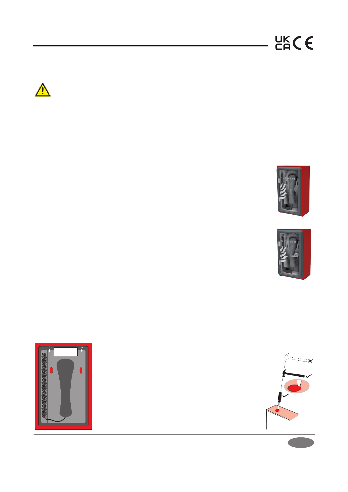
Mounting
Using the four mounting holes provided, fix the outstation to a wall using suitable screw fixings. Any dust or swarf
created during the mounting process must be kept out of the outstation, and care must be taken not to damage any
wiring or components. If a T-BEZ302 bezel is used, then glue the bezel to the hole in the wall using a mastic adhesive.
Approved Document No. DAU0000301 Rev 1 01/05/2023