SignalFire Nodechecker-X Manuel utilisateur
Rev 2.8 SignalFire Telemetry
1
Interface Manual
Node Checker
SignalFire Number: Nodechecker-X
The SignalFire Node Checker has the following features:
-USB powered
-Provides advanced system diagnostics for entire network
-Can display register readings from any node within the network
-Shows wireless signal strength and links for each node
-Wireless configuration of SignalFire nodes
-Optional wireless PACTware/Rosemount Radar Master connection to remote HART devices with
a Sentinel-HART node
Rev 2.8 SignalFire Telemetry
2
Installation
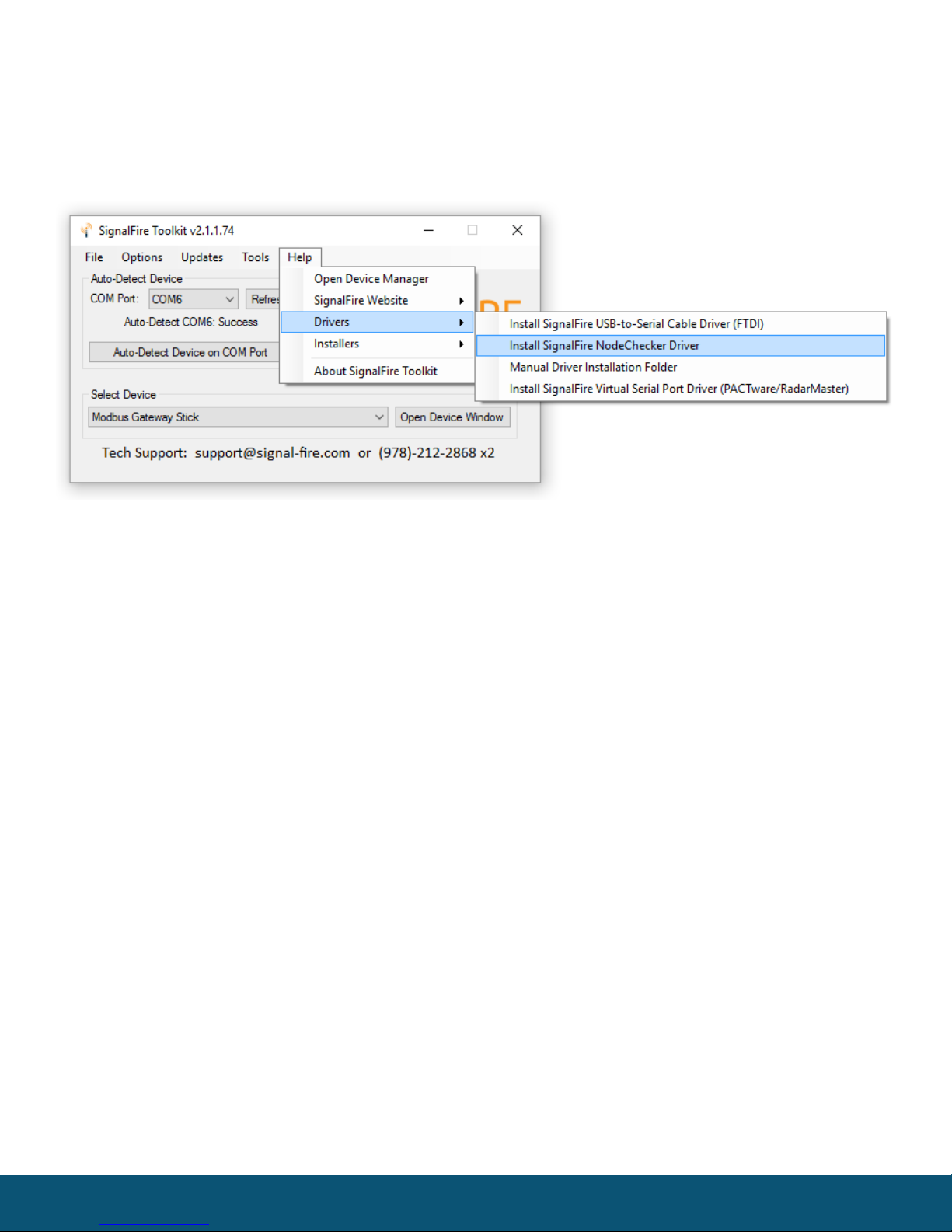
Before connecting the SignalFire Node Checker box to a USB port, open the SignalFire
ToolKit and select Install SignalFire Node Checker Driver from the Help/Drivers menu.
Click ‘Next’ to install the driver.
Rev 2.8 SignalFire Telemetry
3
Using the Node Checker Application
Connect the Node Checker USB cable to the PC. Windows should automatically detect a
new device and install the necessary drivers.
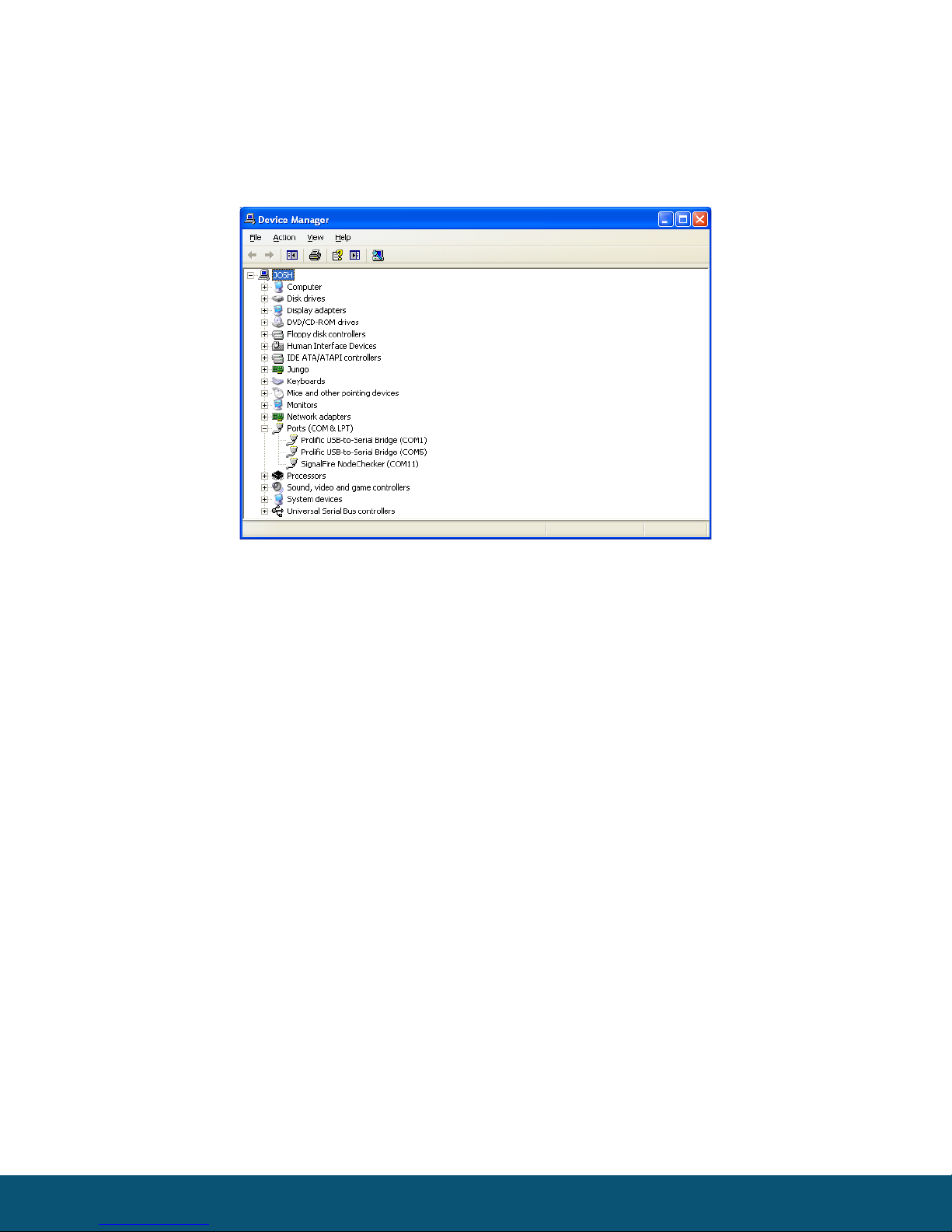
To determine the correct COM port, open the Windows Device Manager and look under Ports. In this
example, the Node Checker is on COM 11.
Note: The DB9 Port on the Node Checker is only used for Node Checker Firmware updates or for use
by the Rosemount Radar Master software.
Note: The Gateway on the network must be running version 7.36 or later to use Node Checker.
Rev 2.8 SignalFire Telemetry
4
Operation
Open the SignalFire Toolkit, select the COM port associated with the Node Checker and
click “Auto-Detect Device on COM Port.” This will open the device configuration window,
where all device settings can be configured. Make sure the Network, Network Group, and
Corporate ID match the network you wish to access.
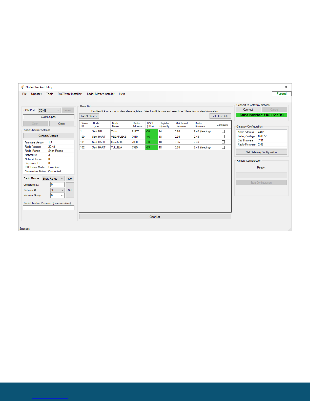
Click Connect. The Node Checker will connect to the configured network, read the gateway
configuration, and list the slave IDs for the nodes connected to the Gateway. To read additional
information from the remote devices highlight one or more rows and click the ‘Get Slave Info’ button.
Double click on any slave ID to see detailed information for that node including versions, battery
voltage, radio link information and register data.
For remote Modbus nodes the user must click add register and enter the register address to poll.
Register maps can be built including descriptions and saved to a file for future list by using the ‘Save
Tags’ and ‘Load Tags’ buttons.
Rev 2.8 SignalFire Telemetry
5
Remote Configuration
The Node Checker supports wireless configuration of a device on the network. Both the
node and the Node Checker must be connected to the network and be within radio range
of each other. It is better to be positioned closer to the node to configure than the
Gateway.
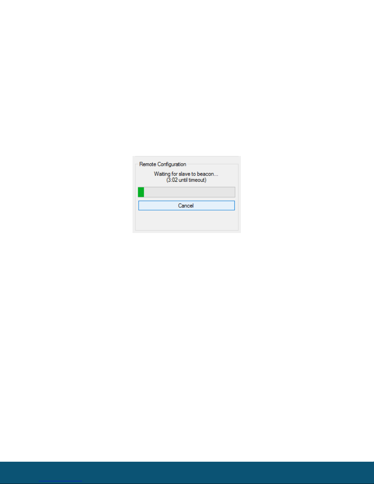
To initiate a configuration session of a node, select the ‘Configure’ checkbox next to one of the nodes
in the list and click the Start Configuration button. If the node has an awake radio the remote
configuration session will be ready start immediately. If it is a sleeping node you must wait for the
node to send a “beacon” so that it can be commanded into configuration mode. The Sentinel nodes
send a beacon every 2.5 minutes, while all other sleeping nodes send a beacon every 5.5 minutes.
A countdown timer will indicate the maximum time left before the node will enter remote
configuration mode. Once the node is awake and ready for configuration click the Open
Configuration Window that will appear.
Only settings applicable to the node type will be available to be changed. To update the configuration
simply change a setting and click the Set button. Clicking Force Device to Check-in to Gateway will
cause the node to read the sensor data and forward it to the gateway. While in remote configuration
mode regular check-ins are disabled, so the Gateway will not receive updated sensor data during the
remote configuration session and may time-out any existing data for that node.
To exit remote configuration mode, return to the main Node Checker window and click on End
Session to return the node to normal operation. The remote configuration session will also
automatically time-out after 10 minutes of inactivity.
Rev 2.8 SignalFire Telemetry
6
Wireless PACTware Mode
If the Wireless PACTware/Radar Master mode has been purchased and unlocked for the
Node Checker box, a wireless PACTware session can be run to a HART sensor connected
to a SignalFire Sentinel Node. The HART sensor must be pre-configured in multidrop
mode and set to HART ID 1.
In order to initiate and run the PACTware session the Node Checker must be within radio range of the
node to configure. It is recommended that the Node Checker is located closer to the node to
configure than the Gateway. The Node Checker must have a good radio direct link to the node to
configure. PACTware cannot be run through a repeater node.
Requirements
-PACTware enabled Node Checker
-PACTware Version 4.1 SP3
-CodeWrights Communication DTM Driver Version 1.0.51 (Supplied by SignalFire)
-Device specific DTMs for the sensor to configure
Installing the CodeWrights Communication DTM Driver
This step must be completed before using PACTware with the Node Checker
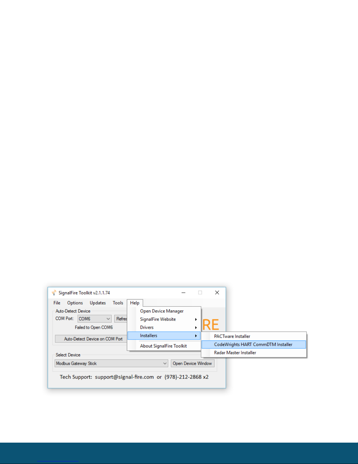
-Download the DTM driver by selecting Download CodeWrights HART CommDTM Installer
from the Installers sub-menu of the Help menu
-

Rev 2.8 SignalFire Telemetry
7
Open the downloaded .ZIP file and run setup.exe
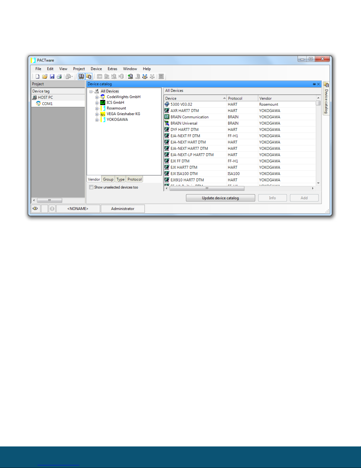
-Once the installation is complete, open PACTware and go to the View menu and
select Device Catalog
-Click on the Update Device Catalog button to install the driver
-Confirm that the CodeWrights GmbH driver appears under the devices menu
Rev 2.8 SignalFire Telemetry
8
Starting a Remote PACTware Session
The following steps are necessary to complete a PACTware session.
1Connect to the network with the Node Checker box
Connect to the network as described in the Node Checker section above
2Start a remote configuration session wait for remote Sentinel node to wake up and beacon
See the remote configuration section
Rev 2.8 SignalFire Telemetry
9
3Launch PACTware
After the node has been placed into remote configuration mode, click on Launch
PACTware 4.1 button in the remote configuration window. This will automatically
open the PACTware application and add the CodeWrights COM DTM to the project
with the correct settings.
4Connect to HART sensor
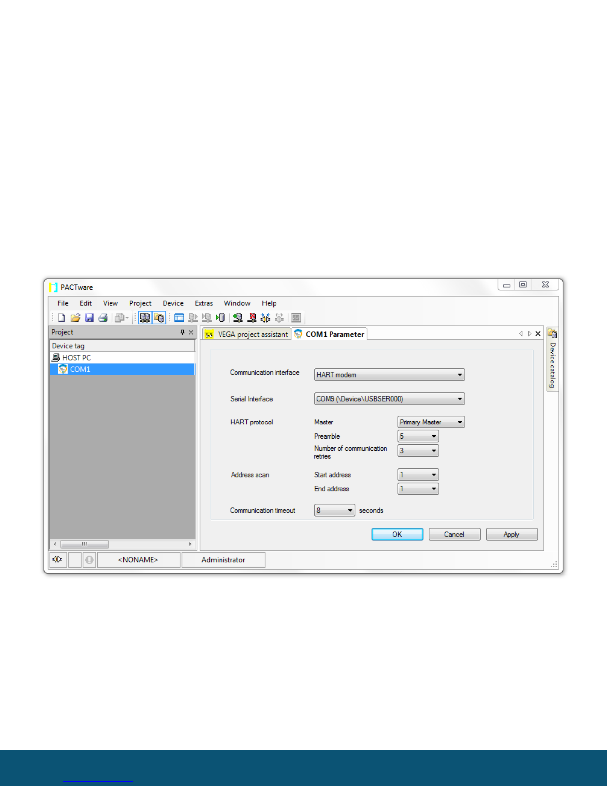
Once PACTware opens, connecting to the HART sensor is different than you may be used to.
-Double click on the COM label under the HOST PC. Select the COM port of the Node
Checker. Click Apply, then click OK (Leave all other settings the way they are).
Rev 2.8 SignalFire Telemetry
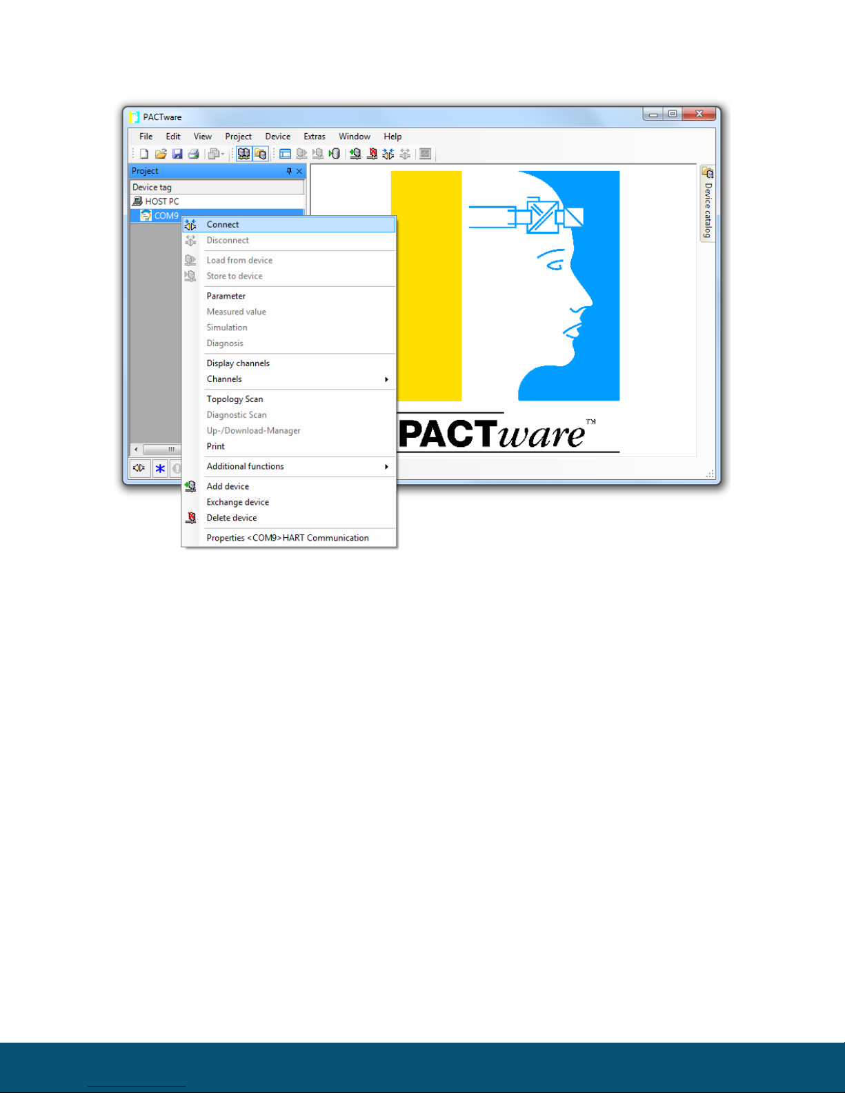
10
-Right click on the COM label and select Connect
Table des matières
Manuels Équipement de test populaires d'autres marques

SMART
SMART KANAAD SBT XTREME 3G Series Manuel utilisateur

Agilent Technologies
Agilent Technologies BERT Serial Manuel utilisateur

Agilent Technologies
Agilent Technologies N3280A Manuel utilisateur

Vernier
Vernier Go Direct Voltage Manuel utilisateur

Lifeloc
Lifeloc R.A.D.A.R. Manuel utilisateur

Fluke
Fluke T5-600 Instructions d'utilisation et d'installation


