SignalFire MIOM Manuel utilisateur
Rev 1.8 SignalFire Telemetry
1
Interface Manual
Modbus Multi I/O Module
SignalFire Number: MIOM
The SignalFire Modbus Multi I/O Module has the following features:
-Standard Modbus RTU server device
-Can be read with a SignalFire Modbus Stick or another Modbus client
-8 analog inputs (0-20mA or 0-5V)
-6 digital inputs (state, counter, and frequency up to 2kHz)
-4 relay outputs (2 DPDT, 2 SPST)
-Internal relay control logic for shutdown applications
-Wide range DC power input. 6 to 36VDC
-Very low power consumption
-DIN Rail mount with pluggable screw terminal blocks
-Status LEDs
-Analog scaling configuration

Rev 1.8 SignalFire Telemetry
2
Specifications
Power
6-36 VDC
5mA max @12V no relays energized, 40mA max @12V with all relays
energized. (excludes current for attached analog sensors)
Operating Temp
-40°C to +80°C
Analog Inputs
0-10V Max
Digital Inputs
Dry Contact or 30 Volts Max
Modbus Comm
Relay Rating
Modbus RTU Server
30 VDC @ 2 Amps
250 VAC @ 0.25 Amps

Rev 1.8 SignalFire Telemetry
3
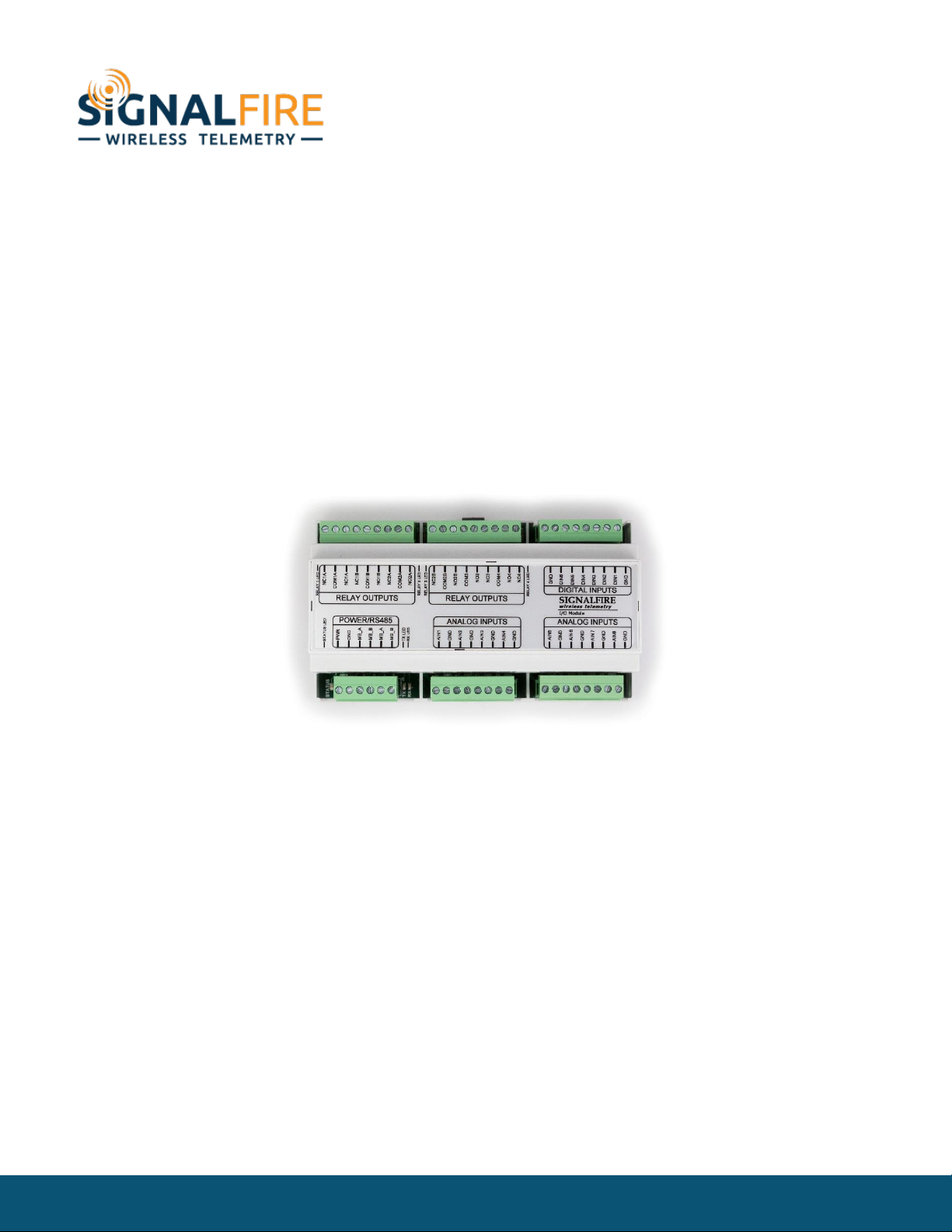
Connections and Components
Modbus Multi I/O Module Connections
The Modbus Multi I/O module provides screw terminals for connection to a RS485
Modbus RTU Client’s A and B terminals. A second set of A/B RS485 terminals are available
for daisy chaining multiply modules or other Modbus devices.
Power must be provided by the Power Input screw terminals (10-30VDC). At 12VDC, the Module
requires only 2mA plus 7.5mA per energized relay channel.
Status LEDs
The Modbus Multi I/O has a green status LED which blinks indicating the module is running. In
addition there are TX/RX LEDs to indicate RS485 messages to/from the Modbus Client.
Each relay output also has a green LED which turns on while the relay is energized.

Rev 1.8 SignalFire Telemetry
4
SignalFire Toolkit Configuration
Connect to the internal 4-pin connection using a SignalFire USB adapter cable. The
module will be auto-detected by the Toolkit. If the module is running “Multi IO System”
firmware it must be loaded with the “Modbus Multi IO Module” to support Modbus
functionality. Clicking on Update Reported Sensor Values will can the data to be refreshed and
displayed. Each relay channel has an Energize and De-Energize button which can be used to toggle
the relay state for testing. In addition, the counters may be zeroed using the tools menu.
Select Standalone Modbus Multi-I/O Firmware and click Start Upgrade to load the Modbus firmware
into the module.

Rev 1.8 SignalFire Telemetry
5
Operation
The SignalFire Modbus Multi I/O Module is intended to be used as a Modbus interfaced
analog and digital input/output (I/O) unit. It allows the user to interface to a variety of
sensor or control devices from a single Modbus port. It is DIN rail mounted and designed
to be easy to use.
Relay Outputs
The four digital outputs will be relays, with two of them being SPDT and two being DPDT.
There are two ways to control the relays:
-Direct control: The PLC writes to a coil register to energize or de-energize the relay.
-Pulse control: The PLC writes to a holding register with a number of seconds to energize the
relay. For example, if you write a 5 to this register, the relay will be energized for 5 seconds and
then automatically de-energized.
Analog Scaling
The Analog Inputs can be scaled so that they will report a 32 bit floating point number. For example, a
4-20mA analog input could be scaled from 0.0 to 5000.0 PSI. In addition each scaled value has an
option offset value (positive or negative) that can be entered and will be applied to the scaled value
result.
Rev 1.8 SignalFire Telemetry
6
Configuration
Modbus ID
The Modbus Multi I/O module requires that the Modbus Server ID be configured either
with the DIP switch or via software. If the DIP switch is set to zero then the Server ID must
be configured in software using either the SignalFire Toolkit or a Modbus write. The DIP switch must
be set to 0 to be configured with the SignalFire Toolkit.
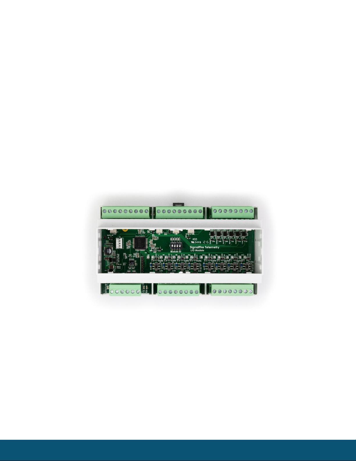
Analog Inputs
The analog inputs may operate in either current (0-20mA/4-20mA) or voltage (0-5V/1-5V). The input
mode must be set by slide switches inside the module. Slide the switch corresponding to the input
channel up to Volts for a voltage input, or down to mA for a current input. To do this, first remove the
cover using a small flathead screwdriver. The cover is held on by clips.
Multi I/O Module with cover removed
Wire the analog voltage or current to the 8 individual sets of screw terminals.
The compliance voltage for a 4-20mA device must be provided externally. The analog current inputs
are passive.

Rev 1.8 SignalFire Telemetry
7
Digital Inputs
The digital inputs (6 total) can be dry contact or voltage (30 Volts max). Be sure to
connect the ground bus from the module to either the ground of the voltage device or
the dry contact.
The frequency of the digital inputs is calculated over a 2-second time period for the
Instantaneous Frequency and calculated over a 60-second window for the Average Frequency. For
example the Average Frequency register will be updated every 60-seconds and will contain the
average frequency of the previous 60-second period.
Digital Input Debounce
In cases where it is desired to accurately totalize digital input counts it may necessary to enable the
“digital input debounce” timer. The debounce timer is useful when dealing with dry contacts that may
otherwise produce extra counts when they close. To enable the digital debounce select “Digital Input
Debounce” from the settings pull-down menu. A typical value for a dry contact would be 100mS. Any
extra counts due to contact bounce within the debounce time setting will be ignored.
Digital (Relay) Outputs
There are four relay outputs. Two of the relays are SPDT and two are DPDT relays. The relays are rated
for the following:
30 VDC @ 2 Amps
250 VAC @ 0.25 Amps
Relay Failsafe Timers
The MIOM supports a configurable failsafe timer which is used to de-energize selected relays in event
of a communication failure.
Relay Message Failsafe Timer –This timer is reset anytime a coil write for any Modbus relay coil write
is received. Each relay can be individually enabled for failsafe operation.
If any timer expires all relays selected for “Failsafe Enable” will be de-energized.
When any relay is de-energized from a failsafe timer it will only be energized when a valid coil write is
received or the relay is commanded on from the Toolkit.
Rev 1.8 SignalFire Telemetry
8
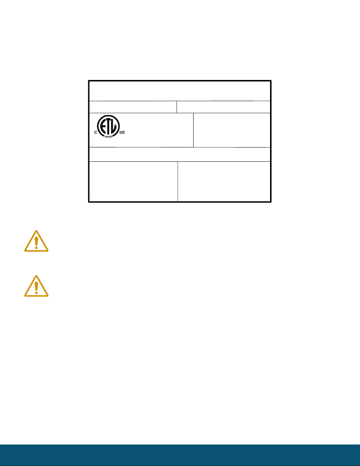
Hazardous Location Certification
The MIOM Module is rated Class 1 Division 2 non-incendive.
Model: MIOM S/N: 00000001
Voltage: 6 –36 VDC
Current: 100 mA Max
Temperature: –40ºC to +85ºC
Class I, Division 2
Groups C, D T4
Hudson, MA
www.signal-fire.com
SignalFire Telemetry
Certified to CSA C22.2 No. 142 and CSA C22.2 No. 213
Conforms to ISA 12.12.01 and UL 916
WARNING –EXPLOSION HAZARD
Substitution of components may impair
suitability for Class I, Division 2
AVERTISSEMENT - RISQUE
D'EXPLOSION. La substitution de
composants peut rendre ce materiel
inacceptable pour les emplacements de classe I,
division 2
WARNING –EXPLOSION HAZARD
Do not connect while circuit is live unless area is
know to be nonhazardous
AVERTISSEMENT - RISQUE D'EXPLOSION.
Ne pas debrancher tant que le circuit est sous
tension, a moins qu’il ne s’agisse d’un emplacement
non dangereux.
Intertek
4003827
WARNING: Exposure to some chemicals may degrade the sealing properties of
materials used in the output relays.
ADVERTISSEMENT: L’exposition à certains produits chimiques peut degrader les
propriétés d’étanchéité de MATERIALS utilizes dans les dispositifs suivants:
-Relais de sortie

Rev 1.8 SignalFire Telemetry
9
Modbus Register Map
Register
Number
Register
Address
Description
Function Codes
Coils (0xxxx)
Read/Write
00102
101
Relay1 Coil
01, 05, 15
00103
102
Relay2 Coil
01, 05, 15
00104
103
Relay3 Coil
01, 05, 15
00105
104
Relay4 Coil
01, 05, 15
Write-only
00112
111
Counter1 Reset Coil
05, 15
00113
112
Counter2 Reset Coil
05, 15
00114
113
Counter3 Reset Coil
05, 15
00115
114
Counter4 Reset Coil
05, 15
00116
115
Counter5 Reset Coil
05, 15
00117
116
Counter6 Reset Coil
05, 15
Discretes (1xxxx)
Read-only
11109
1108
DI1 State
02,
11110
1109
DI2 State
02,
11111
1110
DI3 State
02,
11112
1111
DI4 State
02,
11113
1112
DI5 State
02,
11114
1113
DI6 State
02,

Rev 1.8 SignalFire Telemetry
10
Register
Number
Register
Address
Description
Function Codes
Holding Registers (4xxxxx)
Write-only
40122
121
Relay1 Pulse (0 = Off, 1-255 = Pulse Time (sec))
06, 16
40123
122
Relay2 Pulse
06, 16
40124
123
Relay3 Pulse
06, 16
40125
124
Relay4 Pulse
06, 16
Read-only
41101
1100
AI1: Current or Voltage (Unsigned int, μA or mV)
03, 04
41102
1101
AI2: Current or Voltage Reading
03, 04
41103
1102
AI3: Current or Voltage Reading
03, 04
41104
1103
AI4: Current or Voltage Reading
03, 04
41105
1104
AI5: Current or Voltage Reading
03, 04
41106
1105
AI6: Current or Voltage Reading
03, 04
41107
1106
AI7: Current or Voltage Reading
03, 04
41108
1107
AI8: Current or Voltage Reading
03, 04
41109
1108
DI1: State (Unsigned int, 1 = Closed or 0 = Open)
03, 04
41110
1109
DI2: State
03, 04
41111
1110
DI3: State
03, 04
41112
1111
DI4: State
03, 04
41113
1112
DI5: State
03, 04
41114
1113
DI6: State
03, 04
41115
1114
Relay #1 State (Unsigned int, 1 = ON or 0 = OFF)
03, 04
41116
1115
Relay #2 State
03, 04
41117
1116
Relay #3 State
03, 04
41118
1117
Relay #4 State
03, 04
41119
1118
AI1: Scaled Reading (Float, High Word)
03, 04
41120
1119
AI1: Scaled Reading (Float, Low Word)
03, 04
41121
1120
AI2: Scaled Reading
03, 04
41122
1121
AI2: Scaled Reading
03, 04
41123
1122
AI3: Scaled Reading
03, 04
41124
1123
AI3: Scaled Reading
03, 04
41125
1124
AI4: Scaled Reading
03, 04
41126
1125
AI4: Scaled Reading
03, 04
41127
1126
AI5: Scaled Reading
03, 04
41128
1127
AI5: Scaled Reading
03, 04
41129
1128
AI6: Scaled Reading
03, 04
41130
1129
AI6: Scaled Reading
03, 04
41131
1130
AI7: Scale Reading
03, 04
Table des matières
Autres manuels SignalFire Équipement d'enregistrement

Manuels Équipement d'enregistrement populaires d'autres marques


Strymon
Strymon NIGHTSKY Manuel utilisateur

Mitsubishi Electric
Mitsubishi Electric 16CH DIGITAL RECORDER DX-TL5000U Manuel utilisateur

Tews Technologies
Tews Technologies TPMC465 Manuel utilisateur

Honeywell
Honeywell Excel 50 Manuel utilisateur

SeaLevel
SeaLevel COMM+8.LPCI Manuel utilisateur

Arturia
Arturia AUDIOFUSE STUDIO Manuel utilisateur


