Sigma SDA 2000 Manuel utilisateur

AIR CIRCUT BREAKERS
INSTRUCTION
MANUAL
ISO 2001: 2008

AIR CIRCUIT BREAKERS
www.sigmaelektrik.com
2
ACB
CONTENTS
GENERAL
STRUCTURE
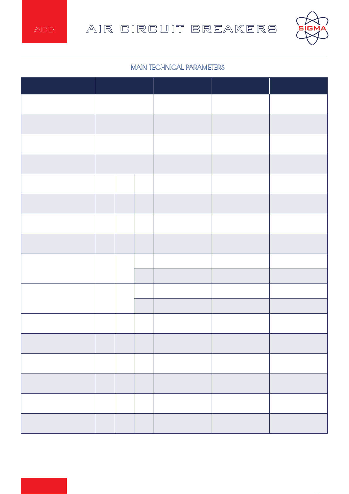
MAIN TECHNICAL PARAMETERS
CHARACTERISTIC OF THE INTELLIGENT CONTROLLER
ACCESSORIS
DIMENSIONS
SECONDARY WIRING DIAGRAM
SETTING VALUE BEFORE LEAVING FACTORY
TROUBLES AND SOLUTIONS
3
3
3
4
5
5
6
7
7

AIR CIRCUIT BREAKERS
www.sigmaelektrik.com
3
ACB
Sınıflandırma
GENERAL
Sigma SFA/SDA series intelligent Air Circuit Breakers are suitable
for use in commercial buildings or industrial plants where safety
and reliability of power supply is an important requirement.
Main Features;
• Fixed and Drawable versions
• Rated current from 630A to 6300A AC and rated voltage of 690 V.
• Short Circuit Breaking Capacity 80kA~120kA (effective value);
• Rated working voltage 690V AC
• Three or four poles;
• Microprocessor controlled intelligent trip unit for all round protection
• Manual or motor operated stored energy drive mechanism for direct or remote actutation.
• Ambient temperature: -5 ~ +40, and average temperature in 24 hours below +35 (except for special orders)
• Comply with EN 60947-2 and VDE 0660.
Environment conditions For Operation and Installation
• Altitude should be less than 2000m.
• Relative humidity: not exceeding 50% at the maximum ambient temperature. higher humidity would be permitted, but the
lowest average temperature in a month not exceeding +35°C during the most moist moth, and the maximum monthly average relative
humidity not exceeding 90% in that month, and giving consideration the dews on the goods surface, which would appear due to
temperature change.
• Pollution degree 3 grade.
• The breakers used on ships can operate reliably under normal vibration.
• The breaker should be installed in compartment of switch - board and door frame should be fixed additionally. Protection grade
is up to IP40

AIR CIRCUIT BREAKERS
www.sigmaelektrik.com
4
ACB
STRUCTURE
Front View Of The Air Circuit Breaker
SDA Series Draw-out Air Circuit Breaker
breakdown showing/return button
handle for manual energy-storage
closing button
energy storage/ energy release indicating
closed / broken showing
face
device for passing in or out
breaking button
handle and its holder position indicator
SDA-6300 SDA-4000 SDA-3200 SDA-2000

AIR CIRCUIT BREAKERS
www.sigmaelektrik.com
5
ACB
Draw-out circuit breaker
1. Terminals of secondary circuit
2. Drawer base
3. Safety separator
4. Handle
5. Terminals of secondary circuit
6. Auxiliary switch
7. Under-voltage release
8. Shunt release
9. Closing electromagnet
10. Operation mechanism
11. Motor-drive charging device
12. Intelligent controller
13. Cover

AIR CIRCUIT BREAKERS
www.sigmaelektrik.com
6
ACB
Position Of Draw-out Type Air Circuit Breakers
Connected position: Main circuit and control circuit are connected.
Test position: The main circuit disconnected and control circuit connected. Testing is possible with the panel door closed.
Disconnected position: The main circuit and auxiliary circuit are disconnected. Safety seperator is closed.
Unit door
Auxiliary circuit is ON
Back of the draw-out socker
Safety seperator
Main circuit is ON
Unit door
Auxiliary circuit is ON
Back of the draw-out socker
Safety seperator
Main circuit is ON
Unit door
Auxiliary circuit is ON
Back of the draw-out socker
Safety seperator
Main circuit is ON

AIR CIRCUIT BREAKERS
www.sigmaelektrik.com
7
ACB
Intelligent controller
Panel caption:
1. Reset button for fault releasing
2. Rated current of the breaker
3. Unit of voltage
4. Voltage indicator
5. Voltage of each line and the min, value
6. Key for selecting voltage
7. Current-time indicator
8. Unit of current and time
Indication of three phase current, neutral phase current,
grounding fault-current and the max. value
9. Key for selecting current
10. "clean " key
11. Fault showing for instantaneous
12. Fault showing for over-load short-delay
13. Fault showing for over-load long-delay
14. Fault showing for earthed error
15. Showing the long-delay current setting
(alarm simultaneously)
16. Showing the long-delay action time setting
17. Showing the short-delay current setting
(alarm simultaneously)
18. Showing the short-delay action time setting
19. Showing the instantaneous current setting
(alarm simultaneously)
20. Key for inspecting fault
21. Key for detecting wearing of contacts
22. Load supervision signal 2 (alarm simultaneously)
23. Load supervision signal 1 ( alarm simultaneously
24. Setting's decrease progressively
25. Setting's increase progressively
26. Supply socket ( DC24V) for test power
27. Memory key
28. Memory indicator
29. Non-release test key
30. Release test key
31. Setting key for various protection value
32. Indication of the earthed fault action time setting
33. Indication of the earthed fault current setting
(alarm simultaneously)
34. Release indicating
35. Test indicating
Other function:
1. Auto-diagnosis
2. Thermo-simulation
3. Fault-memory
4. MCR
The panel here in belongs to the circuit breaker of four poles,
If the breaker is of three poles, the mark IN in item 9 indicating
current of neutral phase will disappear. Other than the type
M intelligent controller with voltage indication, the other one
without voltage indication is also available (there aren't items 3,
4, 5 and 6 on the panel in this case).
NOTE:
AIR CIRCUIT BREAKERS
www.sigmaelektrik.com
8
ACB
Type SDA 2000 / SFA 2000 SDA 3200 / SDA 3200 SDA 4000 / SFA 4000
Kind Of assembly
No Of Poles
3-4 3-4 3-4
Electrical Specifications
Rated Current at 40°ºC A630, 800, 1000, 1250,
1600,2000 2500, 3200 4000
Raqted Voltage Ue V AC 680 680 680
Rated Insulation Voltage Ui V 1000 10000 1000
Rated Impulse Withstand
Voltage Uimp kV 8 8 8
Rated Short-circuit Break-
ing Capacity
Rated Ultimate Short-circuit
Breaking Capacity Icu kA
690 V
AC 50 65 65
415 V
AC 80 100 100
Rated Service Short-circuit
Breaking Capacity Ics kA
690 V
AC 40 50 50
415 V
AC 50 65 65
Category A,B A,B A,B
Pollution degree 3 3 3
Electrical life ope. 415 V 1500 1000 500
Mechanical life ope. 10000 5000 5000
Tripping Unit Electronic Electronic Electronic
Long-time delay current Ir A (0,4-1)xIn (0,4-1)xIn (0,4-1)xIn
MAIN TECHNICAL PARAMETERS
AIR CIRCUIT BREAKERS
www.sigmaelektrik.com
9
ACB
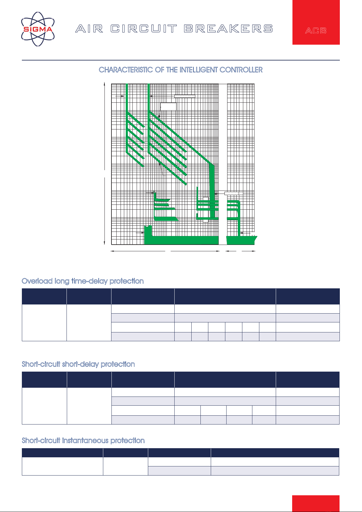
CHARACTERISTIC OF THE INTELLIGENT CONTROLLER
Current ratings
Range (Ir2)
Error Current Actions Time Time Error
(1~15)Ir1
+OFF
(OFF Position)
±10%
≤0.9Ir2 Non-trip
>1.10Ir2 Delayed-trip
Time setting (ts) 0.1 0.2 0.3 0.4 ±15%
Returnable Time 0.06 0.14 0.23 0.35 ±15%
Short-circuit short-delay protection
Current Ratings Range (Ir3) Error Current Action Characteristic
1.0 In~50A/ 75kA/100A
+OFF (OFF Position) ± 15% ≤0.85lr3 Non-trip
>1.15lr3 Trip
Short-circuit instantaneous protection
Current ratings
Range (Ir1) Error Current Actions Time Time Error
(0.4~1)In ±10%
≤1.05Ir1 <2h Non-trip
>1.30Ir1 <1h trip
1.51 Ir1 (setting time) 15 30 60 120 240 480 ±10%
2.0Ir1 8.4 16.9 33.7 67.5 135 270 ±10%
Overload long time-delay protection
Phase N Overload and Over-Current Characteristic 100% or 50% (Applicable to 3p+N or 4P)
30 40 50 60 70 80 100.2 .3 .4 .5 .6 .8 1 2 3 4 5 6 8 10 20
x ln
t (a)
kA
10000
5000
2000
1000
500
200
100
50
20
10
5
2
1
0.5
0.2
0.1
0.05
0.02
0.01
Ir1=(0. 4~1)In
Tr=(15~480)s
I2t
off
Ir2=(I.0~I5)Irl
0.4s
0.3s
0.2s
0.1s
Ir3=1.0In~50kA/75kA/100kA
Over-current protection characteristic curve
ACMIDPAV

AIR CIRCUIT BREAKERS
www.sigmaelektrik.com
10
ACB
Current ratings
Range (Ir4) Error Current Actions Time Time Error
(0.2~0.8)In
+OFF
(OFF Position)
(NA1- 2000,mi-
n160A)
±10%
≤0.9Ir2 Non-tripping
>1.10Ir2 Tripping
Setting time (Tg) 120 240 480 ±15%
Returnable time 67.5 135 270 ±15%
Single phase earth fault protection technical data:
1000
500
100
50
20
10
5
2
1
0.5
0.2
0.1
0.05
0.02
0.01
Ir4=(0.2~0.8)In
xln
t(s)
.05 .06 .08 .1 .2 .3 .4 .5 .6 .8 1 2 3 4 5 6 8 10 20 30
0.4s
0.3s
0.2s
0.1s
0.4s
0.3s
0.2s
0.1s
Earth fault protection characteristic curve
Ce manuel convient aux modèles suivants
4
Table des matières


