Sigma Controls MYRIAD QLC Manuel utilisateur
VISIT OUR WEBSITE SIGMACONTROLS.COM
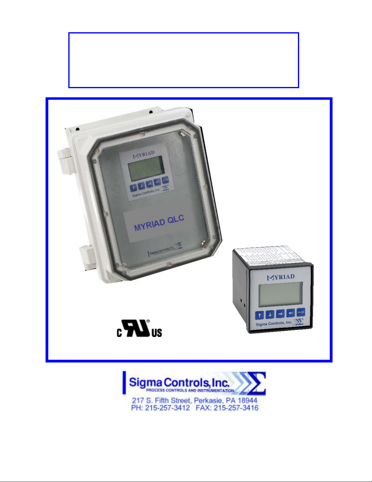
MYRIAD ‘QLC’ 4-CHANNEL
MONITOR/CONTROLLER
INSTRUCTION MANUAL
MYR QLC MANUAL 013114

2
TABLE OF CONTENTS
INTRODUCTION………………………………………… 3
Ordering Information
Specification
Feature
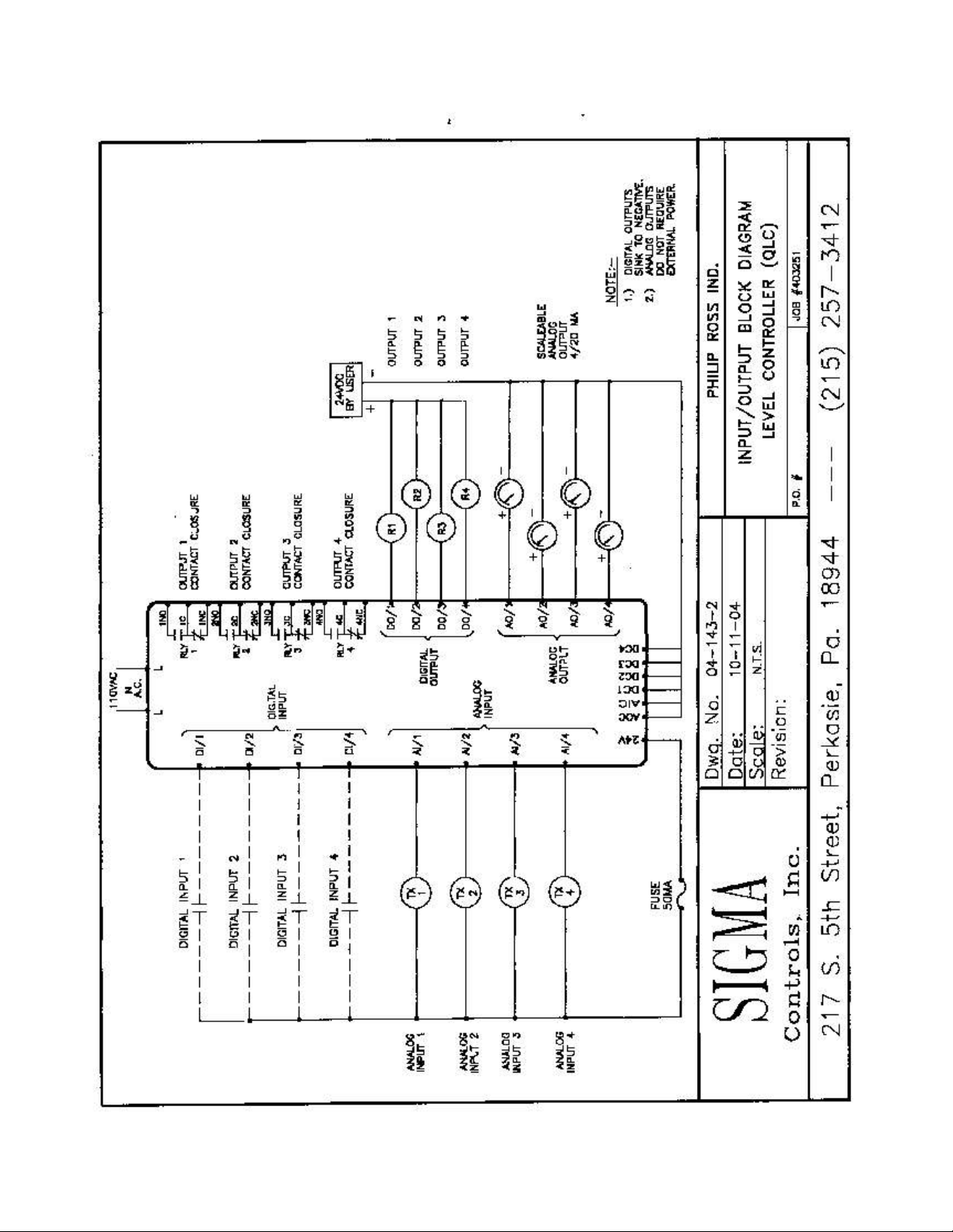
WIRING…………………………………………………… 7
Dwg #: 04-143-2
Analog Input
Analog Output
Digital Input
Digital Output
ROGRAMMING AND INITIAL SETU ……………... 8
Input Range Selection
Terminal Block Detail
Initial Setup & Programming
Overview/Key De cription
TROUBLESHOOTING & MAINTENANCE …………..
15
A ENDIX ‘A’……………………………………………
17
WARRANTY……………………………………………… 18

3
INTRODUCTION:
The Sigma Myriad QLC (Monitor/Controller) i a 4-channel microproce or ba ed, tate of the art,
proce /level monitor/controller offering unmatched performance and full u er configurability.
The QLC i u ed with primary mea uring device , who e input ignal i compatible with common analog
output 4/20MA, 0-5VDC, 1-5VDC, and 0-10VDC.
Proce indication for each channel i di played in both numeric and graphic format on the QLC’ graphic
LCD di play along with the current tatu of the unit’ 4 relay output .
All a pect of the in trument are u er configurable through the ‘plain Engli h’ menu and combination of
the 5 u er data key pu h button .
Available in 2 tyle of mounting, ¼ DIN (4” x 4” nominal) and wall mounted Nema 4X enclo ure , the
Myriad QLC i uitable for in tallation in all indu trial environment .
ORDERING INFORMATION:
1/4 DIN Ca e Sigma Myriad-QLC
Wall Mount Nema 4X Sigma Myriad-QLC-N4X
S ECIFICATIONS:
ANALOG INPUT (4 ea.)
Analog, 4/20MA, 0-5V, 1-5V, 0-10VDC, i olated with common negative, +-0.1% accuracy.
DIGITAL INPUTS (4 ea.)
Digital 10-30V AC or DC, 120 or 240 VAC (require external re i tor).
ANALOG OUTPUT: (4 ea.)
Analog, with common negative 0-20MA, 4/20MA, 0-5V, 0-10V (voltage output require a
re i tor).
DIGITAL OUTPUTS: (4 ea.)
Opto i olated, olid tate, open collector, 100MA 30VDC max.
RELAY OUTPUTS: (4 ea.)
SPDT, Form ‘C’ 5A Relay
DISPLAY:
LCD, 128 X 32 pixel bitmapped graphic di play
LOOP POWER:
24VDC regulated output, 100MA max.

4
5 USER KEYS:
Up, Down, Left, Right, Enter
ACCURACY:
0.1% of calibrated pan
LOCKOUT:
U er pa word, u er configurable
LINEARIZER
20 point programmable for non linear input
INPUT IMPEDANCE:
Voltage 100K, current 100 OHMS
POWER:
120VAC (230VAC available)
ENVIRONMENTAL:
Operating, 0-65° C
Storage, -40° -80° C
R.H., 0-90% non conden ing
ENCLOSURE:
¼ DIN, ABS pla tic 96 X 96 X 150MM
FRONT PANEL:
Ga keted Nema 4X
ACCESS:
Cha i & board remove from front of ca e.
TERMINAL STRIP:
(40) ‘Pluggable’ for ea e of wiring 28 – 16 AWG
CONNECTIONS:
Removable crew terminal block 28 – 16 AWG wire.
CONTROL OUTPUTS:
4 relay output , u er programmable, SPDT Form ‘C’ relay 5 AMP.
4 digital output .
OUTPUT ANNUNCIATION:
On board piezo buzzer
‘WATCHDOG’ CPU ACTIVITY MONITOR

5
PROGRAMMING:
Menu ba ed, all parameter and etpoint are u er configurable via menu prompt and u er key .
The preconfigured creen and ‘pull down’ ub menu with Engli h prompt a ure rapid etup
and commi ioning.
1 YEAR WARRANTY
OPTIONS:
Expan ion card , networking
M.V. NET:
Network allow multiple unit to be connected together for di tributed application , remote
monitoring SCADA application .
EXPANSION CARDS:
Significant expan ion i po ible via additional control board and ‘MV’ networking. (Con ult
factory for detail .)
FEATURES:
Microproce or Ba ed
Graphic LCD Di play
5 Function Key
20 Point Linearization
I olated 24VDC Sen or Power
4/20MA, 1-5V, 0-5V, 0-10VDC Input
4 Analog Input
4 Analog Output
4 Digital Input
4 Digital Output
4 Form ‘C’ Relay Output
Fully U er Programmable in Engli h
2 Ea. RS485 Port (Programming and SCADA)
6
WIRING DETAIL
Input /Output ee Dwg # 04-143-2
CAUTION
!
All electrical wiring must be in accordance with all local state and
national codes that apply.
Do not exceed the rated current of the D.C. power supply (100MA)
or the form ’C’ relay outputs (5A/240VAC resistive).
WARNING
Hazardous voltages are present within the enclosure.
Installation or service should only be carried out by trained
personnel.
7
8
ROGRAMMING & SETU
The Myriad QLC offer multiple ‘Main’ creen allowing the u er to view the four input channel in
different way . The option are a follow :
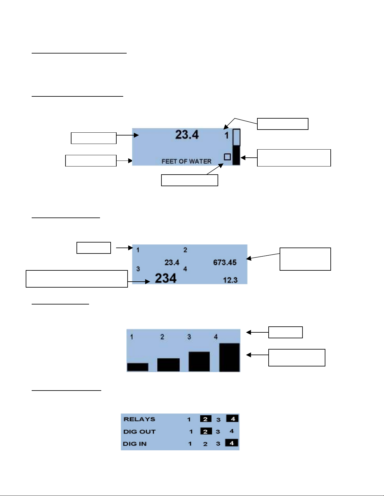
Individual Channel Screens:
Show a elected channel in numeric and graphical format with engineering unit and channel number.
Pre → ← button to advance through each channel in thi format and to the following di play ….
Combination Screen:
Show all channel value in numerical format with channel number indicator .
Bargraph Screen:
Show all four input value a vertical bar graph with channel number .
Digital Status Screen:
Show the tatu of the digital input , relay output and digital output for each channel.
Proce Value
Engineering Unit
Selected Channel #
CPU Activity Monitor
Graphical Proce Indicator
Channel #
Proce value for
channel 2
Di played value will appear larger dependin
g
on the re olution (decimal place) elected.
Channel #
Vertical Bargraph

9
In the example hown above, relay 2 and 4 are active, digital output 2 i active and digital input 4 i
active. Any active point will be indicated a hown.
From any of the tatu creen pre ‘ENTER’ to acce the ‘pa word creen’ and the programming
creen .
Enter u er elected pa word (factory default i zero) with the ↑ ↓ up and down key , then with
→ ← arrow button , move cur or to ‘next’
Pre ‘ ENTER’ to acce menu 1
In thi creen u er acce i provided for.
SCALE – Permit analog caling of each analog input
AOUT - Permit analog caling of each analog output
SETPOINTS - Permit et value for relay and digital output for each channel
DIN - Allow the u er to et the condition of a digital input
With the de ired item highlighted, pre ‘ENTER’ to acce the menu.
Scale:
Pre ‘ENTER’ to elect caling for channel 1 or u e the ↑ ↓ button to elect the de ired channel, pre
‘ENTER’ to acce caling for input 1.
10
U ing the → ← button , croll to ‘NEXT’, pre ‘ENTER’ to move to linearized creen.
NOTE: If the application is linear between minimum input signal and maximum input signal, i.e.
“2 point”, then scroll the cursor to ‘NEXT’ and press ‘ENTER’ to continue the scaling process.
Note on non linear inputs
The Myriad QLC offer a 20 point linearizer which allow the u er to cu tomize the indicated di play for
20 point of input ignal. Thi feature i often u ed to read volume in a non-linear ve el uch a a
horizontal tank with domed end cap . a “ trapping table” mu t be created to allow the di play to be linear
with the re ultant non-linear input ignal.
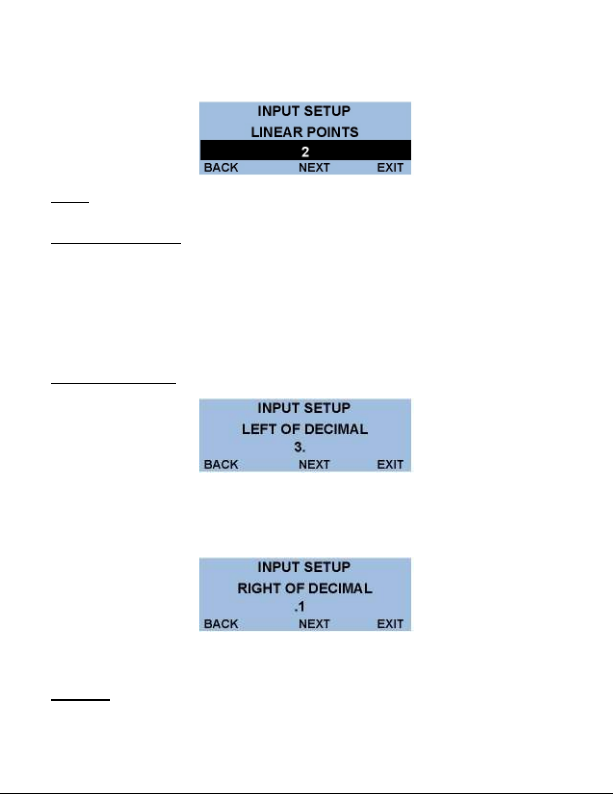
If the u er required a non-linear di play, croll the cur or to “# OF POINTS” and u e the ↑ ↓ arrow to
elect the number of calibration point required, then elect ‘NEXT’ and pre ‘ENTER’ to continue.
Decimal oint Selection:
U e ↑ ↓ button to elect number of digit to be di played to the left of decimal point, croll to ‘NEXT’,
pre ‘ENTER’ and u e thi creen to enter the number digit to appear after the decimal point.
Scroll to ‘NEXT’ and pre ‘ENTER’ to proceed to the ‘Input Text’ creen.
Input Text:
When ‘SCALE MENU’ i complete the ‘INPUT TEXT’ menu i the la t menu in the caling proce .
Table des matières
Autres manuels Sigma Controls Contrôleurs


